
Pinus0079 が 2021年12月26日17時54分13秒 に編集
コメント無し
本文の変更
概要 ==== Arduinoのタイマレジスタ設定についてまとめました。詳しい説明(プログラムの書き方など)については省略します。 Timer0 ====
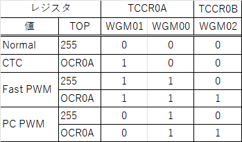
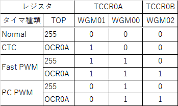
※PC PWM = Phase Correct PWM Timer1 ====
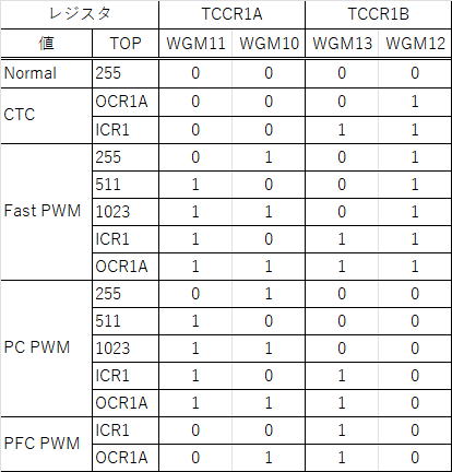
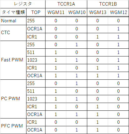
※PC PWM = Phase Correct PWM ※PFC PWM = Phase and Frequency Correct PWM Timer2 ====
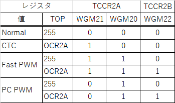
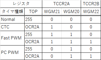
※PC PWM = Phase Correct PWM PWM出力設定 ==== 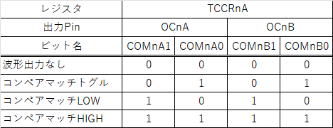 ※n = タイマ番号 分周比 ==== 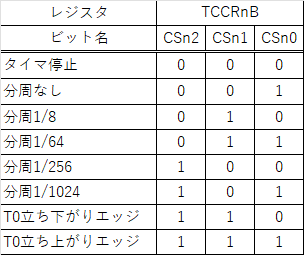 ※n = タイマ番号 周波数の計算式 ==== 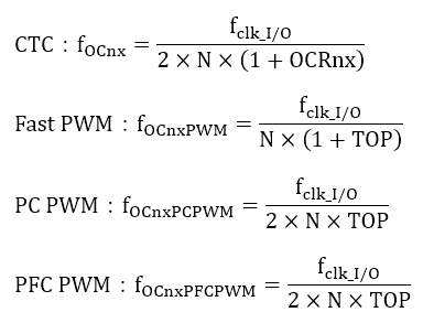 ※n = タイマ番号 ※fclk = クロック周波数(Arduino UNO:16MHz) PWM出力ピンの対応関係 ==== 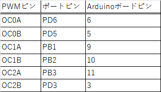 プログラム例 ==== ```arduino:PWM出力設定例 void setup() { pinMode(10,OUTPUT); //OC1B pinMode(9,OUTPUT); //OC1A /*タイマ1初期化*/ TCCR1A = 0; TCCR1B = 0; /* OC1A,OC1B 40kHz出力 * PWMモード:Fast PWM * 分周比:1 * TOP:ICR1 = 400 - 1 * OCR1A:コンペアマッチLOW * OCR1B:コンペアマッチLOW */ TCCR1A |= (1 << WGM11) | (1 << COM1A1) | (1 << COM1B1); TCCR1B |= (1 << WGM13) | (1 << WGM12) | (1 << CS10); ICR1 = 400 - 1; } void loop() { /*OC1A duty比0%出力*/ OCR1A = 0; /*OC1B duty比50%出力*/ OCR1B = 200 - 1; } ``` 最後に ==== タイマ0はdelay関数などで使用されているので、delay関数を使う場合は変更しない方が良いです。 もし間違った箇所があればコメントで教えて頂けるとありがたいです。 参考文献 ==== https://usicolog.nomaki.jp/engineering/avr/avrPWM.html https://ww1.microchip.com/downloads/en/DeviceDoc/Atmel-7810-Automotive-Microcontrollers-ATmega328P_Datasheet.pdf