
RADIO が 2021年02月28日16時39分28秒 に編集
コメント無し
記事種類の変更
製作品
本文の変更
# 概要 CW(モールス信号)トランシーバーを製作中なのですが、それを使用するためにモールス符号を出力するための装置が必要になるので作ってみました。 モールス信号を出力するための装置を「電鍵」と言いますが、モールス信号と聞くと、よく映画などで登場するこのような電鍵を想像される方が多いと思います。  この電鍵を「縦振れ電鍵」と言います。縦振れ電鍵は構造が簡単なのですが、短点と長点(・と-)を自分で作る必要がありリズム感が掴めていない初心者が扱うのは難しいようです。 そこで、「エレクトリック・キーヤー」という電鍵を製作しました。製作物の全景です。 画像準備中 画像のように、今回製作したエレクトリック・キーヤーは、「パドル」と呼ばれる2枚の板が付いたレバーと、マイコンを使用した電子回路となっています。 # 機能 エレクトリック・キーヤーは、パドルの片側を押すと短点、その逆側を押すと長点が出力されます。また、押し続けると、それぞれが連続して出力され(・・・…または---…)、同時に押すと短点と長点が交互に出力されます(・-・-・-…)。これらは、マイコンにより正確なリズム(短点 : 長点 = 1 : 3)で出力されるので、初心者でもきれいなモールス符号を打つことができます。 # パドルの製作 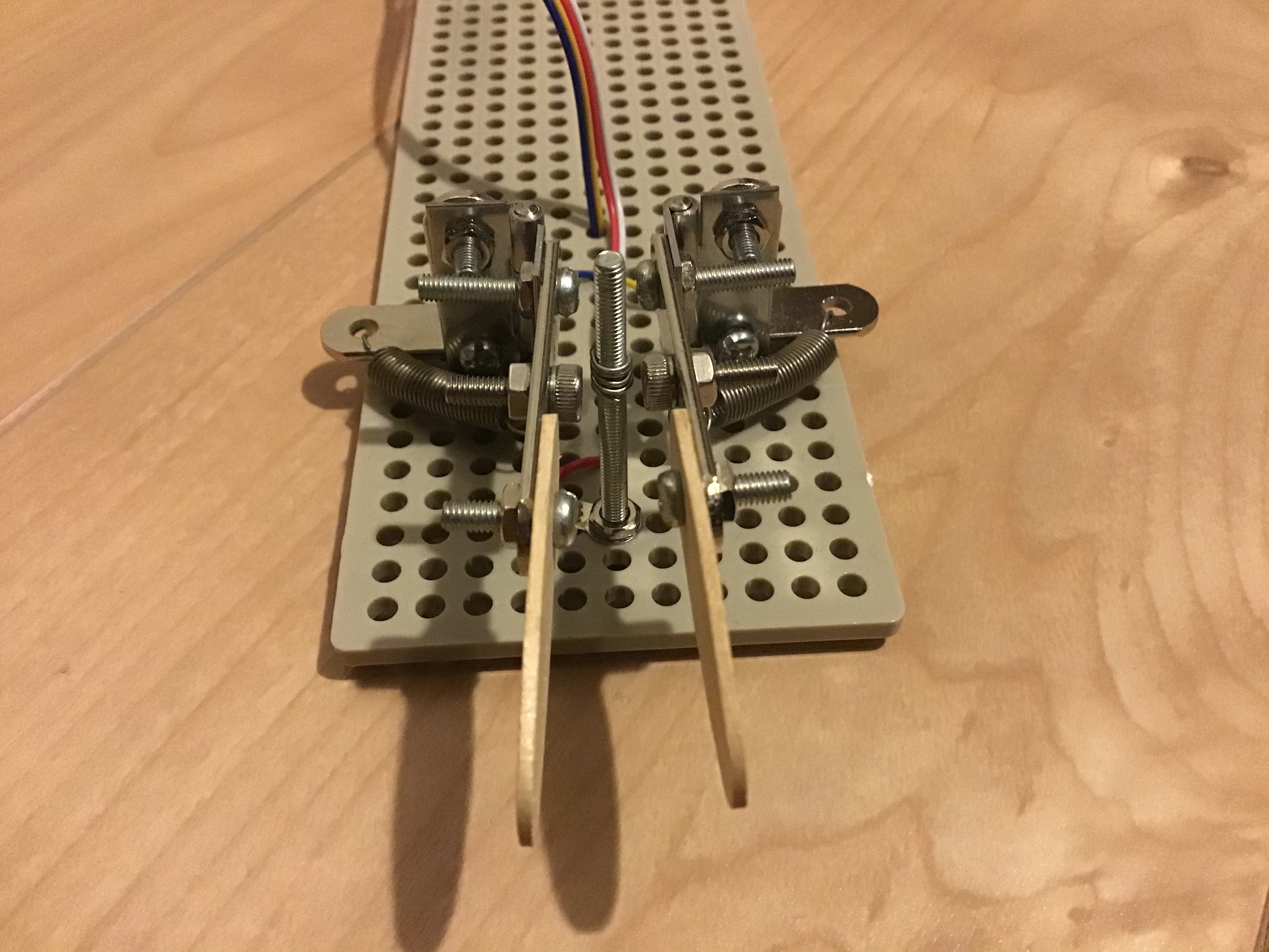 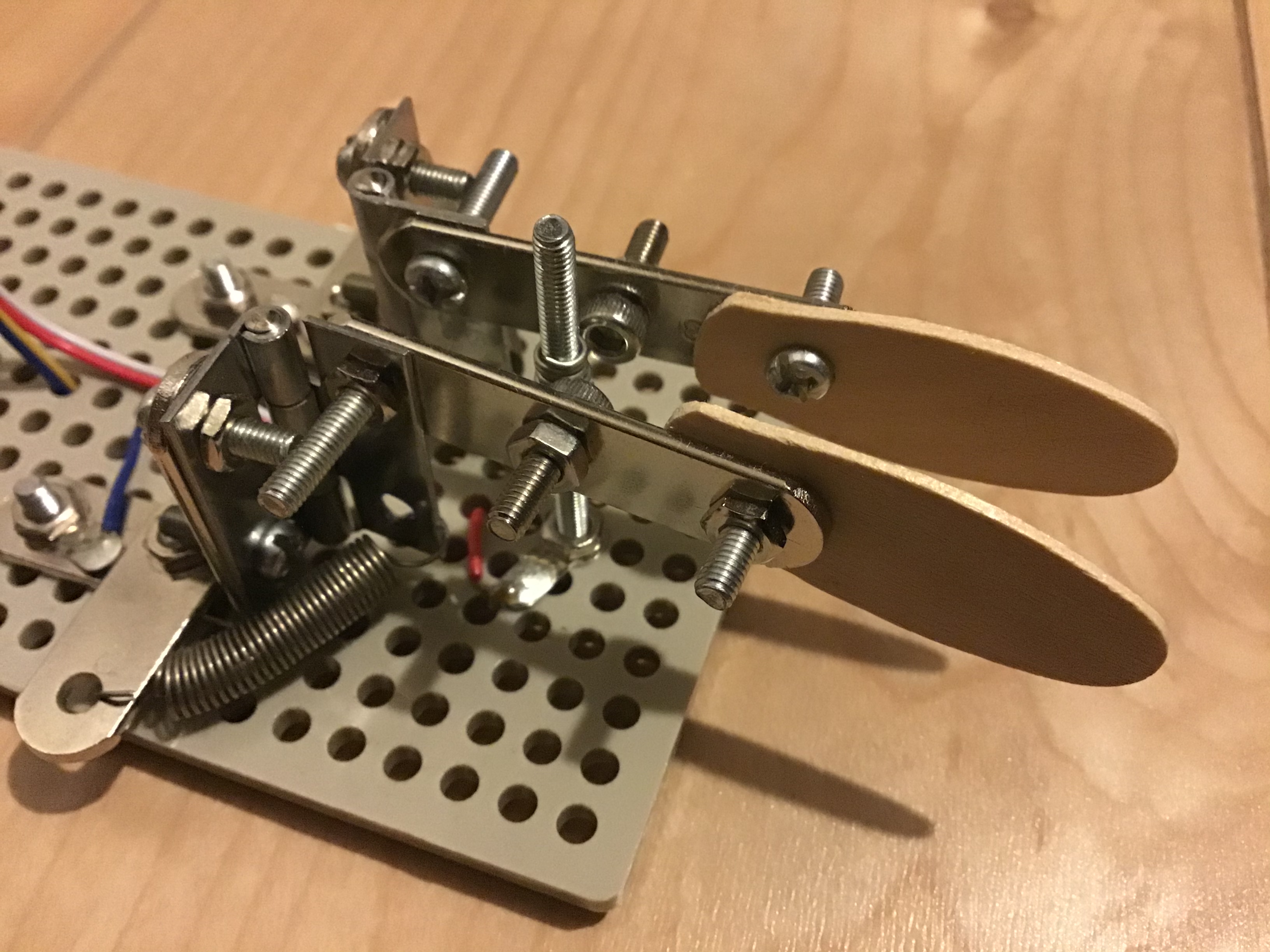 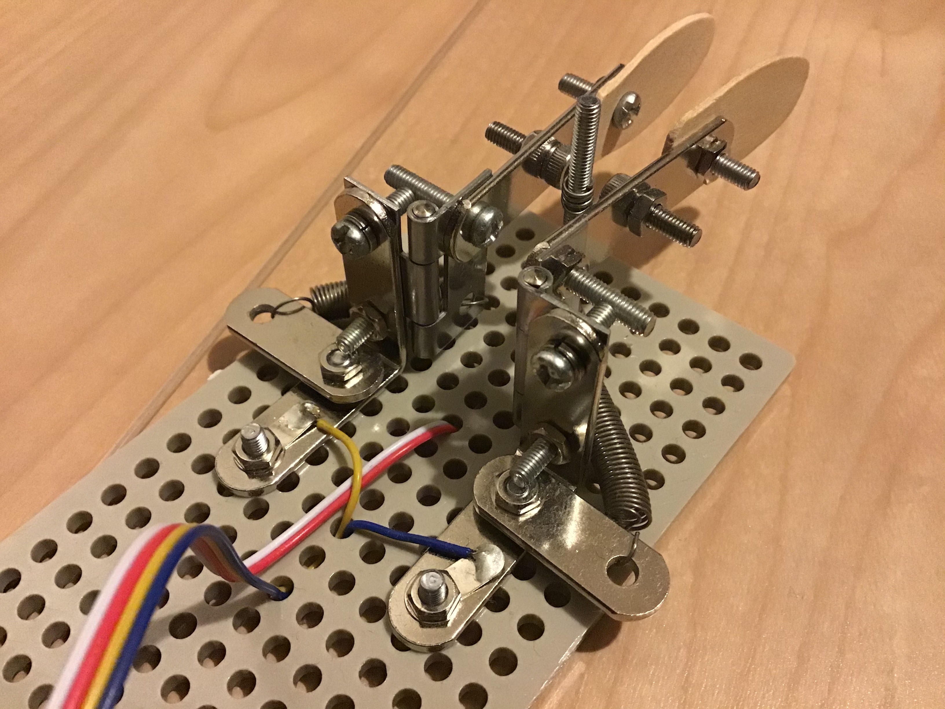 池上さん(JA1UXR)のHP(「cw パドル 自作」で検索)で紹介されていたパドルを参考に、蝶番、バネを使用して制作しました。 持ち手の部分はアイスに付いている木製スプーンを加工して作りました。 中央の接点は、40mmのボルトを使用していますが、接触が悪いのでスズメッキ線を接点に巻きつけています。 台座はタミヤのユニバーサルプレートを使用しています。 # 回路図 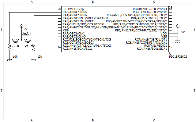 マイコンはPIC18F23K22を使用しています。 パドル中央の接点へ常に電源電圧が加えられていて、レバーはプルダウンされているので押すとHIGHとなります。 # プログラム ``` // PIC18F25K22 Configuration Bit Settings // 'C' source line config statements // CONFIG1H #pragma config FOSC = INTIO67 // Oscillator Selection bits (Internal oscillator block) #pragma config PLLCFG = OFF // 4X PLL Enable (Oscillator used directly) #pragma config PRICLKEN = ON // Primary clock enable bit (Primary clock enabled) #pragma config FCMEN = OFF // Fail-Safe Clock Monitor Enable bit (Fail-Safe Clock Monitor disabled) #pragma config IESO = OFF // Internal/External Oscillator Switchover bit (Oscillator Switchover mode disabled) // CONFIG2L #pragma config PWRTEN = ON // Power-up Timer Enable bit (Power up timer enabled) #pragma config BOREN = SBORDIS // Brown-out Reset Enable bits (Brown-out Reset enabled in hardware only (SBOREN is disabled)) #pragma config BORV = 190 // Brown Out Reset Voltage bits (VBOR set to 1.90 V nominal) // CONFIG2H #pragma config WDTEN = OFF // Watchdog Timer Enable bits (Watch dog timer is always disabled. SWDTEN has no effect.) #pragma config WDTPS = 32768 // Watchdog Timer Postscale Select bits (1:32768) // CONFIG3H #pragma config CCP2MX = PORTC1 // CCP2 MUX bit (CCP2 input/output is multiplexed with RC1) #pragma config PBADEN = OFF // PORTB A/D Enable bit (PORTB<5:0> pins are configured as digital I/O on Reset) #pragma config CCP3MX = PORTB5 // P3A/CCP3 Mux bit (P3A/CCP3 input/output is multiplexed with RB5) #pragma config HFOFST = OFF // HFINTOSC Fast Start-up (HFINTOSC output and ready status are delayed by the oscillator stable status) #pragma config T3CMX = PORTC0 // Timer3 Clock input mux bit (T3CKI is on RC0) #pragma config P2BMX = PORTC0 // ECCP2 B output mux bit (P2B is on RC0) #pragma config MCLRE = INTMCLR // MCLR Pin Enable bit (RE3 input pin enabled; MCLR disabled) // CONFIG4L #pragma config STVREN = ON // Stack Full/Underflow Reset Enable bit (Stack full/underflow will cause Reset) #pragma config LVP = ON // Single-Supply ICSP Enable bit (Single-Supply ICSP enabled if MCLRE is also 1) #pragma config XINST = OFF // Extended Instruction Set Enable bit (Instruction set extension and Indexed Addressing mode disabled (Legacy mode)) // CONFIG5L #pragma config CP0 = OFF // Code Protection Block 0 (Block 0 (000800-001FFFh) not code-protected) #pragma config CP1 = OFF // Code Protection Block 1 (Block 1 (002000-003FFFh) not code-protected) #pragma config CP2 = OFF // Code Protection Block 2 (Block 2 (004000-005FFFh) not code-protected) #pragma config CP3 = OFF // Code Protection Block 3 (Block 3 (006000-007FFFh) not code-protected) // CONFIG5H #pragma config CPB = OFF // Boot Block Code Protection bit (Boot block (000000-0007FFh) not code-protected) #pragma config CPD = OFF // Data EEPROM Code Protection bit (Data EEPROM not code-protected) // CONFIG6L #pragma config WRT0 = OFF // Write Protection Block 0 (Block 0 (000800-001FFFh) not write-protected) #pragma config WRT1 = OFF // Write Protection Block 1 (Block 1 (002000-003FFFh) not write-protected) #pragma config WRT2 = OFF // Write Protection Block 2 (Block 2 (004000-005FFFh) not write-protected) #pragma config WRT3 = OFF // Write Protection Block 3 (Block 3 (006000-007FFFh) not write-protected) // CONFIG6H #pragma config WRTC = OFF // Configuration Register Write Protection bit (Configuration registers (300000-3000FFh) not write-protected) #pragma config WRTB = OFF // Boot Block Write Protection bit (Boot Block (000000-0007FFh) not write-protected) #pragma config WRTD = OFF // Data EEPROM Write Protection bit (Data EEPROM not write-protected) // CONFIG7L #pragma config EBTR0 = OFF // Table Read Protection Block 0 (Block 0 (000800-001FFFh) not protected from table reads executed in other blocks) #pragma config EBTR1 = OFF // Table Read Protection Block 1 (Block 1 (002000-003FFFh) not protected from table reads executed in other blocks) #pragma config EBTR2 = OFF // Table Read Protection Block 2 (Block 2 (004000-005FFFh) not protected from table reads executed in other blocks) #pragma config EBTR3 = OFF // Table Read Protection Block 3 (Block 3 (006000-007FFFh) not protected from table reads executed in other blocks) // CONFIG7H #pragma config EBTRB = OFF // Boot Block Table Read Protection bit (Boot Block (000000-0007FFh) not protected from table reads executed in other blocks) // #pragma config statements should precede project file includes. // Use project enums instead of #define for ON and OFF. #include <xc.h> #include <pic18f25k22.h> #define _XTAL_FREQ 16000000 int t = 0; int a = 0; int LONG = 0; int SHORT = 0; int LONGstart = 0; int SHORTstart = 0; int idling = 1; int n = 100; int frag = 0; void PICsetup(){ OSCCON = 0b01110010; ANSELA = 0b00000000; ANSELB = 0b00000000; ANSELC = 0b00000000; TRISA = 0b00000011; TRISB = 0b00000000; TRISC = 0b00000000; LATA = 0b00000000; LATB = 0b00000000; LATC = 0b00000000; } void delay(int msecond){ int t = 0; while(t < msecond){ __delay_ms(1); t++; } t = 0; } void TIMERsetup(){ T2CON = 0b00000101; //タイマー2有効 1μsで1カウント PR2 = 100; //100μsで割り込み発生 TMR2 = 0; //タイマー2レジスタの初期化 TMR2IF = 0; //フラグ初期化 TMR2IE = 1; //タイマー2割り込み許可 GIE = 1; //割り込み許可 PEIE = 1; //周辺機器の割り込み許可 } void __interrupt () TIMER(){ GIE = 0; if(TMR2IF == 1){ TMR2IF = 0; LONG = PORTAbits.RA0; SHORT = PORTAbits.RA1; t = t+1; a = 1; } GIE = 1; } void check(){ if(SHORT){ frag = 1; } } void LONG_function(){ LONGstart = 0; t = 0; LATBbits.LATB0 = 1; while(t<10*n); while(t<30*n){ check(); } t = 0; LATBbits.LATB0 = 0; while(t<10*n){ check(); } t = 0; if(SHORT == 1 || frag == 1){ SHORTstart = 1; frag = 0; }else if(LONG){ LONGstart = 1; }else{ idling = 1; } } void SHORT_function(){ GIE = 0; SHORTstart = 0; LATBbits.LATB0 = 1; t = 0; delay(n); LATBbits.LATB0 = 0; t = 0; delay(n); t = 0; GIE = 1; delay(1); if(LONG){ LONGstart = 1; }else if(SHORT){ SHORTstart = 1; }else{ idling = 1; } } int main (){ PICsetup(); TIMERsetup(); while(1){ if(idling){ if(a){ if(LONG){ LONGstart = 1; idling = 0; }else if(SHORT){ SHORTstart = 1; idling = 0; } a = 0; } }else{ if(LONGstart){ LONG_function(); }else if(SHORTstart){ SHORT_function(); } } } } ```
タイミングはタイマー割り込みを使って処理していますが、短点の時間の処理はdelayで行っています。はじめ、短点もタイマー割り込みで時間を測っていましたが、誤作動することが多く、チャタリングの影響を疑って短点を押した段階で、割り込みを禁止するようにしたためです。長点を押した場合はなぜか誤作動が起きないのでそのままにしています。
タイミングはタイマー割り込みを使って処理していますが、短点の時間の処理はdelayで行っています。はじめ、短点もタイマー割り込みで時間を測っていましたが、誤作動することが多く、チャタリングの影響を疑って短点を押した段階で、割り込みを禁止するようにしたためです。長点を押した場合はなぜか誤作動が起きないのでそのままにしています。 # アルゴリズム :::plantuml:短点 @startuml (*)-->"短点が押される" -->"n秒出力" if "長点が押されてる?" then -->"n秒待つ" -->"長点の処理へ" else if"短点が押されている?"then -->"n秒待つ1" -->短点が押される else -->"n秒待つ2" -->"アイドリング状態へ" -- @enduml ::: :::plantuml:長点 @startuml (*)-->"長点が押される" -->"3n秒出力" if "短点が押されてる?" then -->"n秒待つ" -->"短点の処理へ" else if"長点が押されている?"then -->"n秒待つ1" -->長点が押される else -->"n秒待つ2" -->"アイドリング状態へ" -- @enduml ::: 長点が押されたとき、「短点が押されてる?」の判定は3n秒出力されているうち後半のn秒間で行われます。