tanolabo が 2022年09月25日16時15分18秒 に編集
初版
タイトルの変更
SPRESENSEをカードエッジタイプの小型モジュール化して使いやすくしてみた
タグの変更
デジタルアンプ
マイク
I2Sデジタルオーディオ
SPRESENSE
FRISK
メイン画像の変更
記事種類の変更
製作品
ライセンスの変更
(MIT) The MIT License
本文の変更
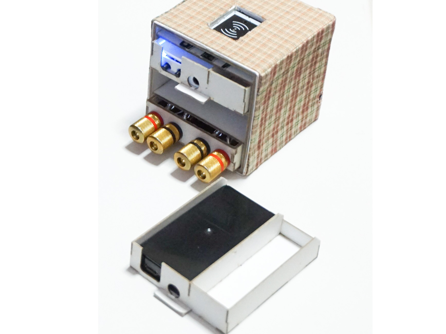
**概要** == SPRESENSE MAINボードの強力なオーディオ機能を簡単に活用するため、 必要な端子だけを取り出したカードエッジ型モジュールを製作しました。 モジュール化により簡単に使いまわしできるようになり、 他のモジュールと組み合わせて様々なオーディオ機器を作ることができます。 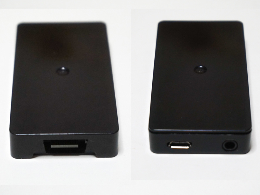 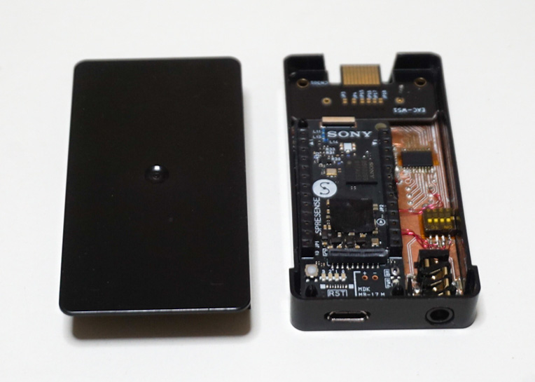 今回製作したのは、I2S入力デジタルAMPモジュールです。 SPRESENSEのデジタルAMP機能を使っています。 センサーと組み合わせることにより今後の拡張が可能です。 音量はカードエッジのGPIO端子にSWを接続して制御します。 I2Sデジタル音声信号はスマホのストリーミング音源から 別途作成したBluetoothモジュールより入力しました。 ++Bluetoothモジュールの詳細は別投稿を参照してください。++ 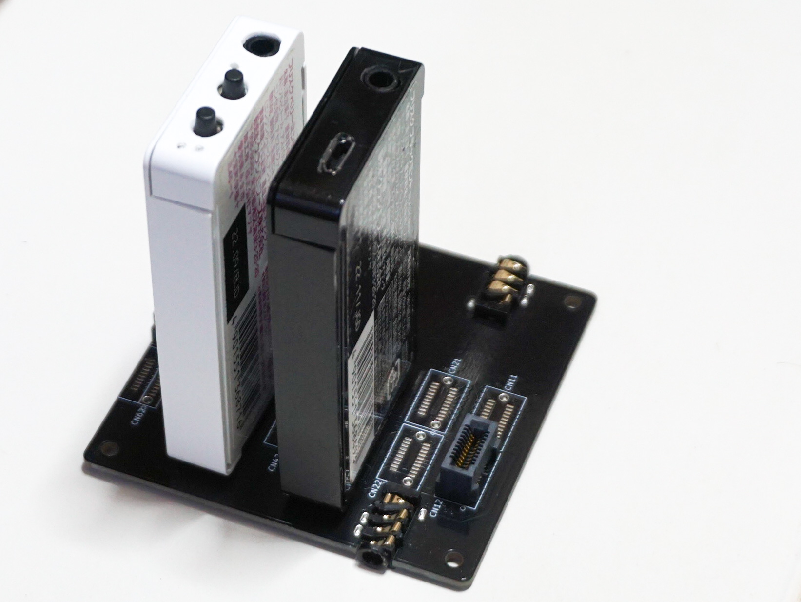 **特徴** == - L70xD37xH11の小型ケースに収納 - カードエッジ端子の入出力信号は変更可能 - カードエッジ端子のVBUSから電源供給可能 - 4極オーディオジャック(MIC端子有)を搭載 - I2S信号入力/アナログオーディオ信号出力 SPRESENSEの低消費電力と使い回せるモジュール構成により ECOなオーディオシステムをDIY可能です。 **構成** == 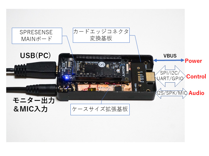 1. SPRESENSE MAINボードでスピーカーを直接ドライブするため、SPRESENSEハードウェアガイドの[1.18. スピーカーの使用方法](https://developer.sony.com/develop/spresense/docs/hw_docs_ja.html#_HOW_TO_USE_SPEAKERS)を参考にして部品交換を行います。 ++ここに記載のはんだ作業を行った場合には、いかなる場合であっても製品保証の対象外となります。ご自身の責任において実施してください。++ 2. ケースサイズの拡張ボード 標準の拡張ボードより小さくし、小型ケースに納まる拡張ボードを作成しました。 音楽保存やプログラム拡張用のMicroSDカードはSPRESENSEの下へ配置しています。 SPRESENSEに接続したUSB給電とカードエッジのVBUS給電に対応しています。 DC-DC電源を搭載しカードエッジ信号はレベル変換ICにより3.3V接続としました。 [SPRESENSE拡張ボードの回路図](https://github.com/sonydevworld/spresense-hw-design-files/raw/master/CXD5602PWBEXT1/schematics/CXD5602PWBEXT1_schematics.pdf)を参考にAudio機器製作に必要な信号を40pinコネクタでカードエッジ変換基板へ接続しています。 ++掲載した写真は試作基板ですが今後P板化する予定です。++ 3. カードエッジコネクタ変換基板 変換基板の役割は3つです。 - 信号選択 カードエッジ端子は小型化のため表裏で20pinとなります。 拡張基板からの40pinコネクタの信号から必要な信号を変換基板で20pinカードエッジ端子へ接続しています。 変換基板を交換する事で必要な信号を選択でき、様々なシステムに柔軟に対応することができます。 - 高さ調整 カードエッジコネクタが、ケースの高さのセンター位置になるように高さ1.5mmのB2Bコネクターを使用しました。 - コスト削減 金メッキ端子の基板は高価なので基板サイズを小さくして単価を下げました。 ++掲載した写真はI2S-アナログコンバータ用の変換基板です。++ **設計図** == - 拡張ボードの回路図 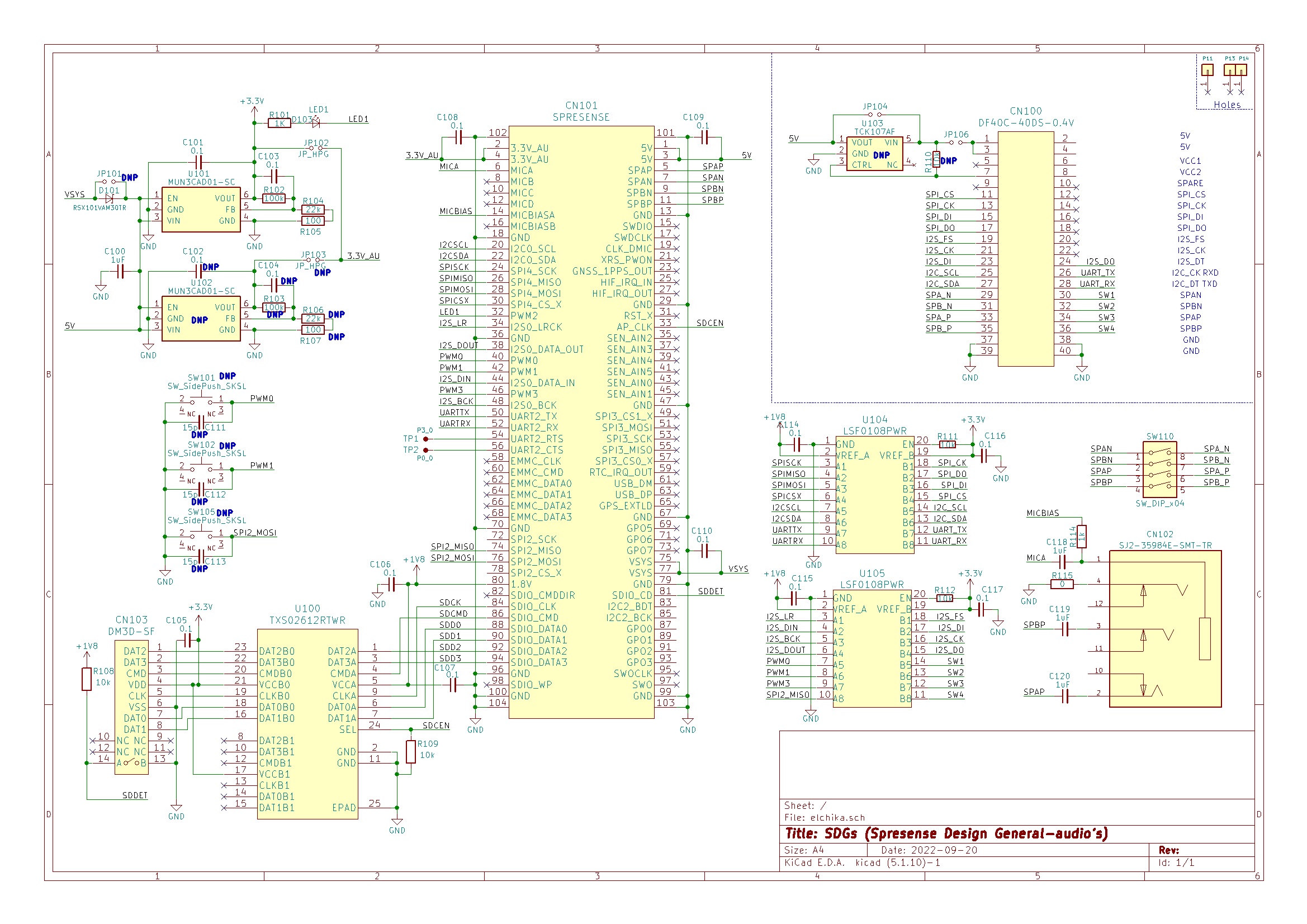 - 変換基板の回路図 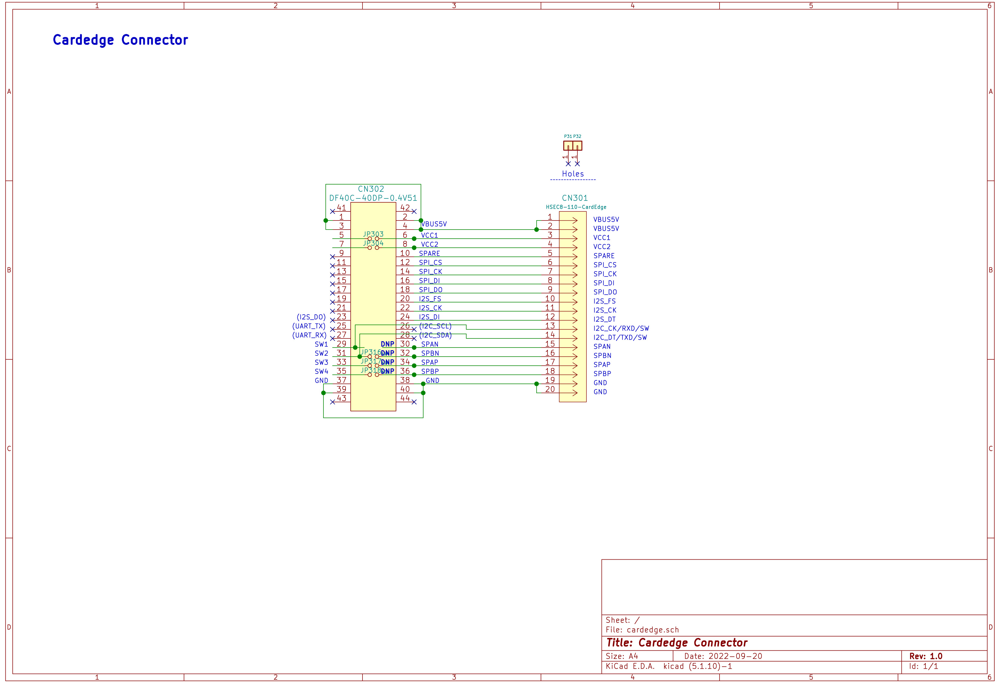 **部品** == 主要な使用部品リストです。REFは回路図を参照してください(DNP/CR類を除く) - 拡張基板 | REF | 部品 | 備考 | |:--:|:--|:--| |CN100| DF40C-40DS-0.4V | 40pinコネクタ (変換基板接続用) | |CN101| DF40C-100DS-0.4V |100pinコネクタ (SPRESENSE接続用) | |CN102| SJ2-35984E-SMT-TR | 3.5インチ4極ミニジャック (モニター/MIC用) | |CN103| DM3D-SF | MicroSD用コネクタ | |U100| TXS02612RTWR | レベル変換 (MicroSD用) | |U101| MUN3CAD01-SC | DC-DCコンバータ (3.3V用) | |U104| LSF0108PWR | レベル変換 (CardEdge信号用) | |U105| LSF0108PWR | レベル変換 (CardEdge信号用) | |D101| RSX101VAM30TR | ショットキーダイオード (VSYSブリッジ用) | - 変換基板 | REF | 部品 | 備考 | |:--:|:--|:--| |CN301| Cardedge基板パターン|20pin金メッキパターン(HSEC8-110用) | |CN302| DF40C-40DP-0.4V |40pinコネクタ (拡張基板接続用) | - ケース FRISKのケースを使用しました。 最近は取り扱い店舗が少なくなっているようです。 **ソースコード** == 今回は、ArduinoのSPRESENSE用スケッチ例にあるthrough.inoを修正しました。 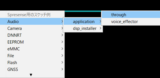 - 音量は最大の "AS_SP_DRV_MODE_4DRIVER"へ変更しました。 - 音量調整ボタンは、カードエッジ端子からPUSHSWを接続している信号に合わせて、PIN_D03とPIN_D05を使用しました。 ```arduino:修正例 /* * through.ino - Through mode(I2S <=> Analog) example application * Copyright 2018 Sony Semiconductor Solutions Corporation * * This library is free software; you can redistribute it and/or * modify it under the terms of the GNU Lesser General Public * License as published by the Free Software Foundation; either * version 2.1 of the License, or (at your option) any later version. * * This library is distributed in the hope that it will be useful, * but WITHOUT ANY WARRANTY; without even the implied warranty of * MERCHANTABILITY or FITNESS FOR A PARTICULAR PURPOSE. See the GNU * Lesser General Public License for more details. * * You should have received a copy of the GNU Lesser General Public * License along with this library; if not, write to the Free Software * Foundation, Inc., 51 Franklin St, Fifth Floor, Boston, MA 02110-1301 USA */ #include <Audio.h> AudioClass *theAudio; #define MAX_VOLUME 50 #define MIN_VOLUME -500 static int currentVolume = -400 ; static int loopcount = 0; /** * @brief Audio attention callback * * When audio internal error occurc, this function will be called back. */ static void audio_attention_cb(const ErrorAttentionParam *atprm) { puts("Attention!"); if (atprm->error_code >= AS_ATTENTION_CODE_WARNING) { exit(1); } } /** * @brief Setup audio through to I2s input to speaker * * Set output device to speaker <br> * Set input mic gain to 16.0 dB */ void setup() { pinMode(PIN_D03, INPUT_PULLUP); pinMode(PIN_D05, INPUT_PULLUP); /* start audio system */ theAudio = AudioClass::getInstance(); theAudio->begin(audio_attention_cb); puts("initialization Audio Library"); /* Set input source with first argument. * The second argument means source of I2s output. * If you set "I2sIn" as the first argument, please set "None" as the second argument. * Set speaker driver mode to LineOut with last argument. * If you want to change the speaker driver mode to other, * specify "AS_SP_DRV_MODE_1DRIVER" or "AS_SP_DRV_MODE_2DRIVER" * or "AS_SP_DRV_MODE_4DRIVER" as an argument. * */ int err = theAudio->setThroughMode(AudioClass::I2sIn, AudioClass::None, true, 160, AS_SP_DRV_MODE_4DRIVER); if (err != AUDIOLIB_ECODE_OK) { printf("Through initialize error\n"); exit(1); } theAudio->setVolume(-300); if (err != AUDIOLIB_ECODE_OK) { printf("Set Volume error\n"); exit(1); } } /** */ void loop() { if (loopcount % 5 == 0) { loopcount = 0; if (digitalRead(PIN_D05) == LOW) { if (currentVolume < MAX_VOLUME) { currentVolume += 10; printf("Set Volume++ %d\n", currentVolume); } theAudio->setVolume(currentVolume, 0, 0); delay(10); loopcount++; } else if (digitalRead(PIN_D03) == LOW) { if (MIN_VOLUME < currentVolume) { currentVolume -= 10; printf("Set Volume-- %d\n", currentVolume); } theAudio->setVolume(currentVolume, 0, 0); delay(10); loopcount++; } } else { loopcount++; } } ``` **応用** == - バックプレーン基板によりモジュール間を接続することができます。 - 様々な拡張モジュールを作成してオリジナルのオーディオシステムを構成できます。 (電源モジュール、NFCモジュール、赤外線リモコンモジュール、音声制御モジュール、LCD表示モジュールなど) - MICを接続してスピーカー含めたF特を調整できるようにする予定です。