
masayasan が 2021年10月18日20時23分47秒 に編集
初版
タイトルの変更
PICでI2C接続小型キャラクタLCDモジュールの制御
タグの変更
PIC
タミヤカムロボット
I2C
LCD
本文の変更
# 概要 秋月電子で購入出来るI2C接続LCDをPICで制御します。 取敢えずは文字と変数の表示。 現在制作中のタミヤカムロボットのI2Cポートに空きがあったので、それを利用しました。 シリアルモニタ使ってるのであまり必要性が無いのですが、2足歩行ロボットなどのモーション作成する時に重宝するので、忘備録として残します。 ## 「AQM1602XA-RN-GBW」 I2C接続小型キャラクタLCDモジュール 16×2行 3.3V/5V「AQM1602XA-RN-GBW」 カタカナ表記が出来る優れものです。秋月電子で購入しました。450円/個 また電源電圧3.1~5.5Vで使いやすいです。 # MCC I2C接続する際、SDA,SCLピンをプルアップします。 マイコンの種類によっては"Easy Setup"だけではなく"Registers"側にプルアップを有効にする項目もあります。 今回使用しているPIC16F18857は"Easy Setup"の設定だけで良いです。 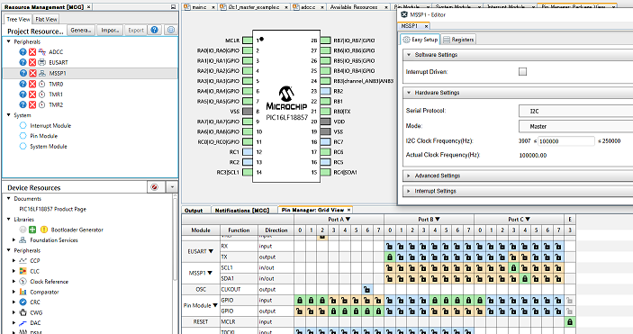 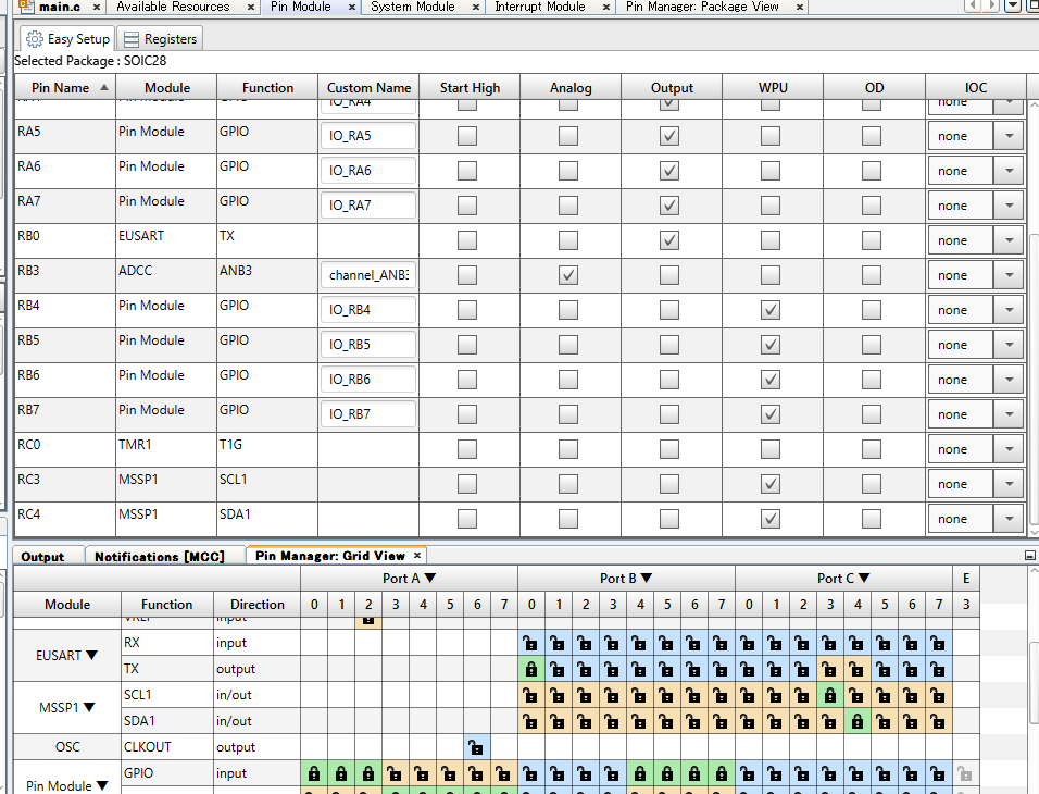 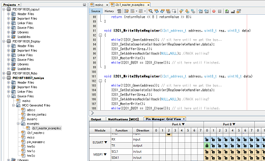 # プログラム I2C通信にはMCCで自動製作された ”uint8_t I2C1_Read1ByteRegister(i2c1_address_t address, uint8_t reg)”関数を使用します。 ``` #include "mcc_generated_files/mcc.h" #include "mcc_generated_files/examples/i2c1_master_example.h" #define LCDadd 0x3e void init_LCD() { __delay_ms(100); I2C1_Write1ByteRegister(LCDadd, 0x00, 0x38); __delay_ms(20); I2C1_Write1ByteRegister(LCDadd, 0x00, 0x39); __delay_ms(20); I2C1_Write1ByteRegister(LCDadd, 0x00, 0x14); __delay_ms(20); I2C1_Write1ByteRegister(LCDadd, 0x00, 0x73); __delay_ms(20); I2C1_Write1ByteRegister(LCDadd, 0x00, 0x52); __delay_ms(20); I2C1_Write1ByteRegister(LCDadd, 0x00, 0x6C); __delay_ms(20); I2C1_Write1ByteRegister(LCDadd, 0x00, 0x38); __delay_ms(20); I2C1_Write1ByteRegister(LCDadd, 0x00, 0x01); __delay_ms(20); I2C1_Write1ByteRegister(LCDadd, 0x00, 0x0C); __delay_ms(20); } void LCD_int(int val, int c) { char buf[12]; // int c = sizeof(buf); snprintf(buf, 12, "%d", val); for (int i = 0; i < c; i++) { I2C1_Write1ByteRegister(LCDadd, 0x40, buf[i]); //LCDadd 0x3e } } void LCD_char(char buf[], int c) { for (int i = 0; i < c; i++) { I2C1_Write1ByteRegister(LCDadd, 0x40, buf[i]); //LCDadd 0x3e } } void main(void) { SYSTEM_Initialize(); init_LCD(); while (1) { int Vale = ADCC_GetSingleConversion(channel_ANB3); init_LCD(); LCD_char("アカルサ ",6); LCD_int(Vale, 4); __delay_ms(300); } } ``` ”void init_LCD()”関数はマニュアル参考に製作しました。実行すると画面が初期化されます。 ”void LCD_int(int val, int c) ” と”void LCD_char(char buf[], int c)”関数もマニュアルを参考に製作しました。 変数を表示させるには”void LCD_int(int val, int c)”を使用し、valに変数名、cに桁数。 文字を表示させるには”void LCD_char(char buf[], int c)”を使用し、charに文字列、cに文字数。 カタカナ表示の場合は半角で入力してください。 機能として流れる様に文字をシフトさせたりも出来る様なので、LCDライブラリとして色々な機能を準備して置いたら便利かもしれません。 # 動画 照度センサーで読み取った明るさをLCDで表示させてみました。 暗いほど数値が小さくなります。 照明を直接当てると900以上の数値を示しますが、部屋の照明では150-200でした。 アナログ値の分解能が0-1023なのを考慮すると分圧抵抗器は選定し直した方が良さそうですね。 PICの内部抵抗で十分か? @[youtube](https://youtu.be/Jt7qB_gnE1A) # まとめ 今後、LCDモニタを使った面白い電子工作を思いついたら何か制作してみようと思います。