reopeo0526 が 2025年01月31日21時37分34秒 に編集
コメント無し
本文の変更
# はじめに 皆さんはドローンで遊んだことはありますか? 最近は小型で手のひらサイズの物もたくさんあります。 自分もオープンソースで安価な「M5Stamp Fly」を買って試してみました。 ドローン自体はとってもおもしろいのですが、動くものを手にしたら**自動操縦**させたくなるのが制御屋の性 ということで、ドローン側にはほぼ手を加えず外部から認識して着陸を自動で行うシステムを作ってみました! (SFによく出てくる母艦に着艦するときにコントロールを譲渡するアレ...) 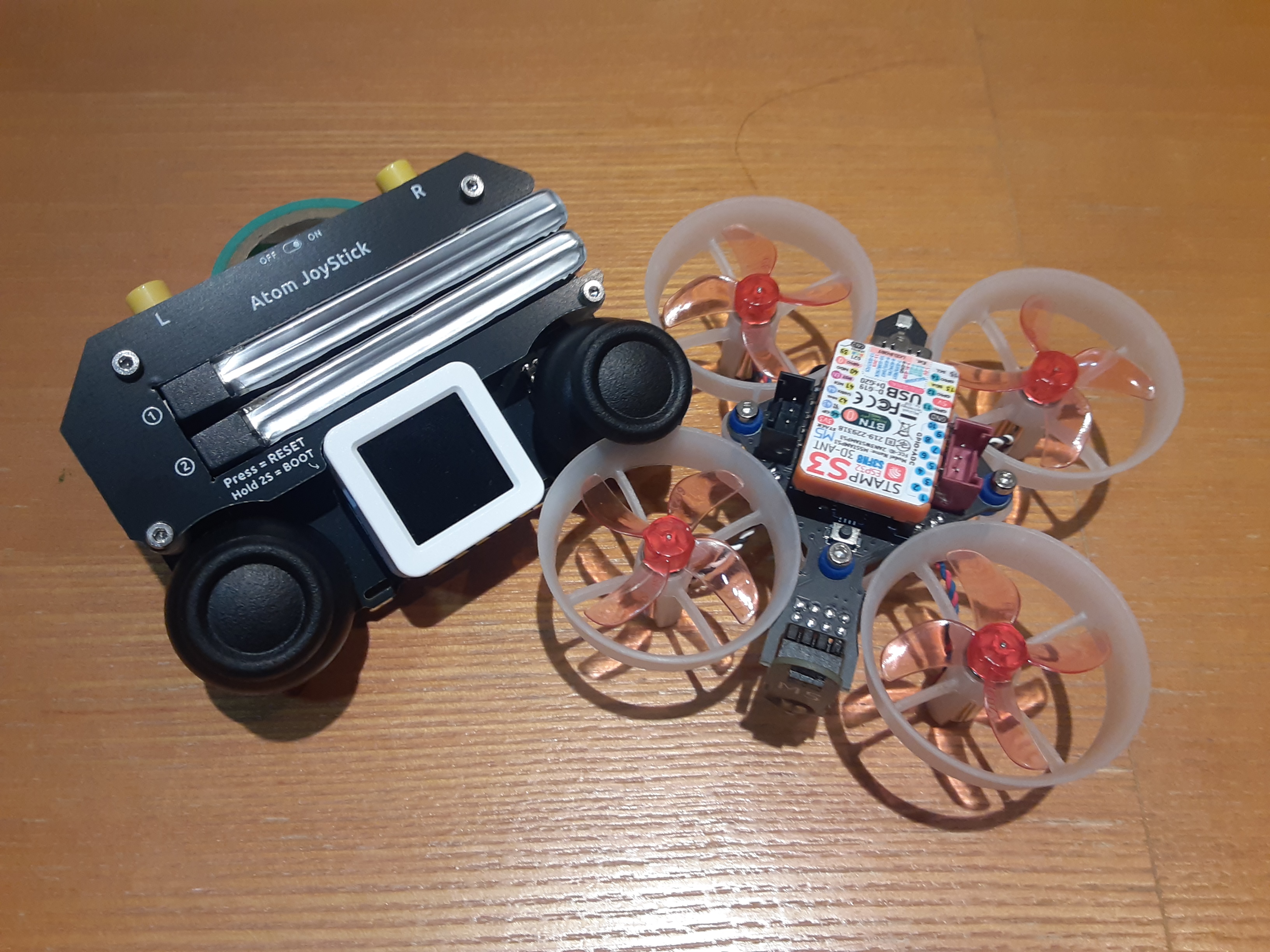 # 全体像 全体的なシステムの構想はこんな感じです。 1. HDRカメラを接続したSPRESENSEをドローンパッドの中心に配置 2. Spresenseに組み込んだAIでドローンの姿勢(x,y,theta)を認識し、I2CでAtomS3に送信 3. AtomS3は認識結果をディスプレイに表示し、姿勢の偏差が0になるようにドローンを制御 # 部品等 Spresense メインボード Spresense 拡張ボード SDカード (16GB) M5Stamp Fly M5Atom Joystick M5 ATOMS3 モバイルバッテリ ブレッドボード ジャンパーワイヤー 適当な段ボール Spresenseは公式で紹介されているAruduino-IDE、M5系はPlatform-IOで開発しました。 # 作成手順 ## 回路作成 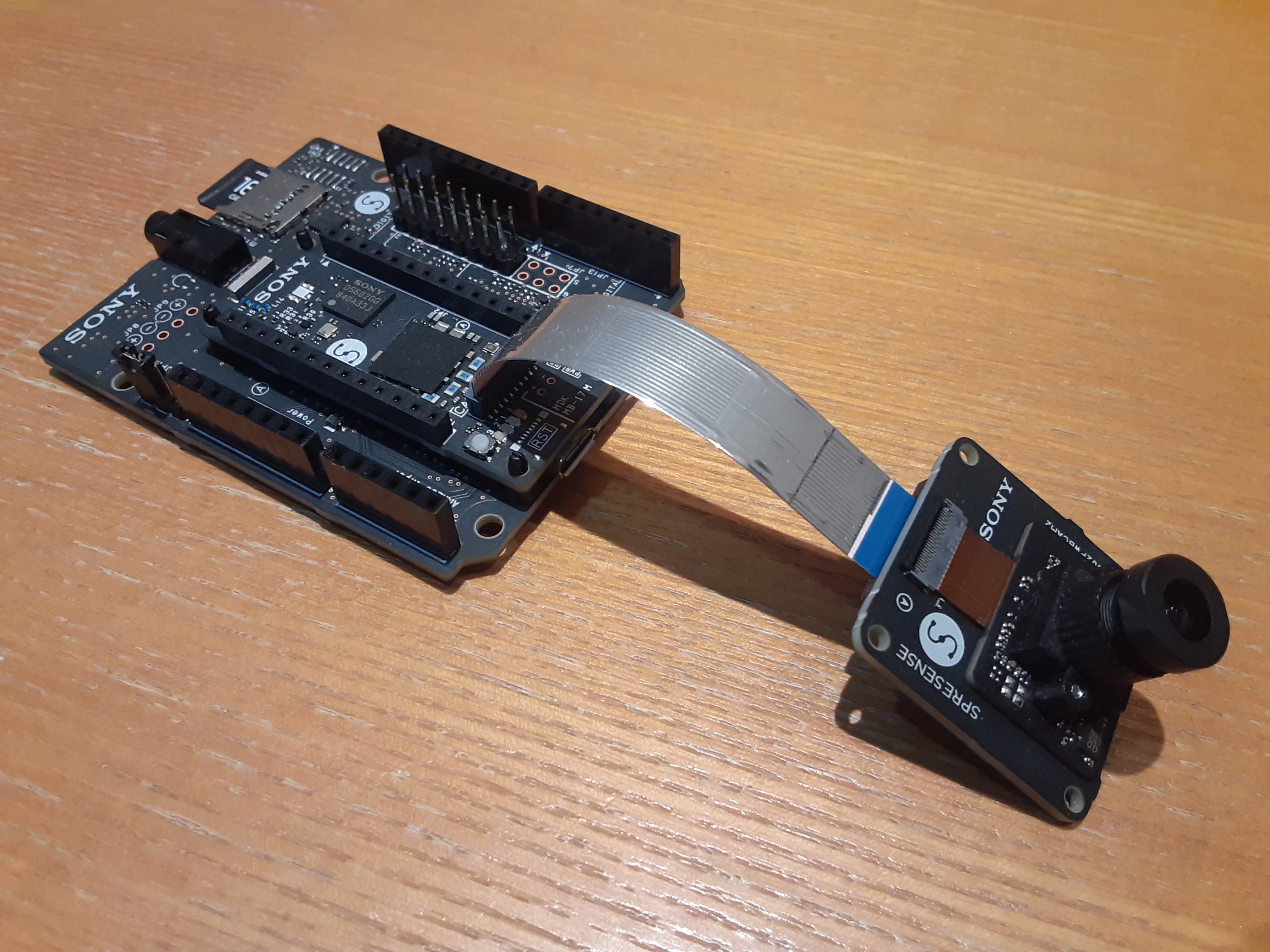 Spresense側の構成は、メインボード・拡張ボード・HDRカメラを合体させたものにSDカードを差して完成です。 Spresenseで画像認識させるための基本的な構成です。 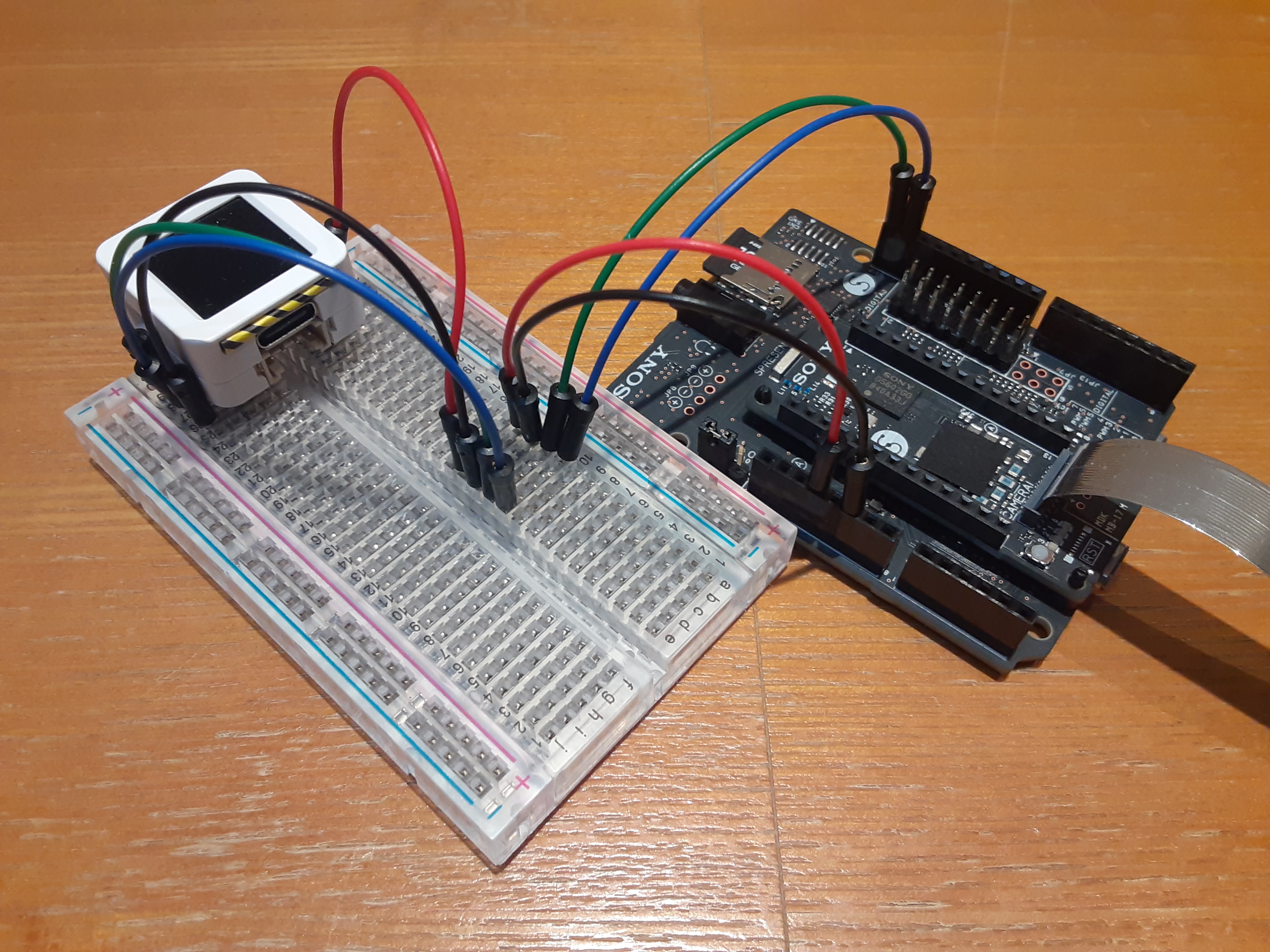 また、ドローンへデータを送信したり認識結果を表示するためにAtomS3を使います。 電源供給とI2C通信ができるように接続します。 ## ドローンパッド制作 上記で作成した回路にドローンを降下させるため、着陸台(ドローンパッド)を作ります。 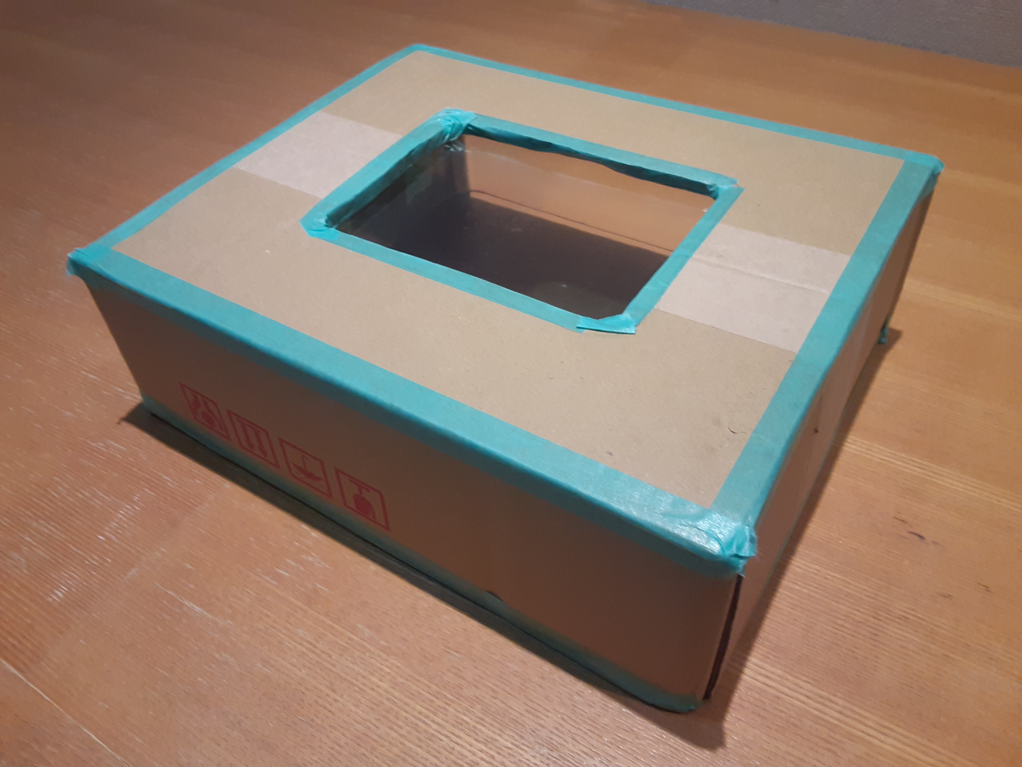 今回は穴を開けた適当なダンボールにドローンを買ったときについてきた透明なケースを貼り付けました。 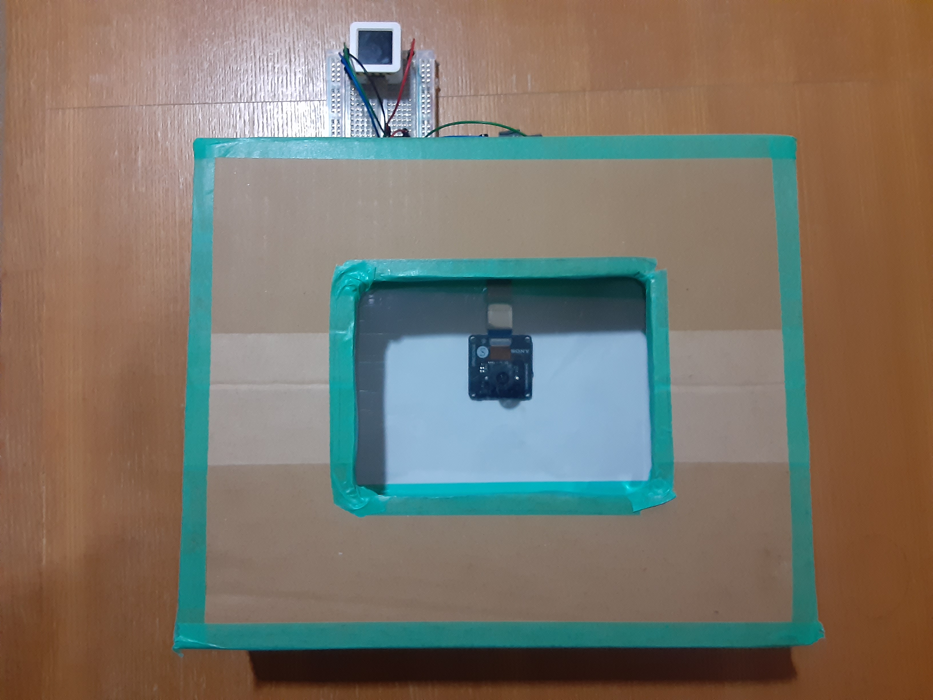 HDRカメラが水平になるように設置したら、上からドローンパッドをかぶせてハード面は完成です! ## 学習用データセットの作成 ### SDカードへの保存 学習用の画像を集めるために一定間隔で画像を撮影し、SDカードに保存するスクリプトを作りました。 どんな画像が保存されているかを確認するため、AtomS3に撮影画像を送信し確認できるようにしています。 ==エッジAIではどれだけ本番環境に近いデータを集められるかが重要なので実際に使う場所で準備する== **spresense側** ```Arduino:live_camera_sd.ino #include <Arduino.h> #include <Camera.h> #include <Wire.h> #include <SDHCI.h> #include <File.h> #define RAW_IMG_W CAM_IMGSIZE_QQVGA_H #define RAW_IMG_H CAM_IMGSIZE_QQVGA_V #define RESIZE_IMG_W RAW_IMG_W / 4 #define RESIZE_IMG_H RAW_IMG_H / 4 #define SLAVE_ADDRESS 0x08 #define MAX_I2C_BYTES 32 #define I2C_DELAY 8 SDClass SD; int count = 0; float calc_array[RESIZE_IMG_W * RESIZE_IMG_H]; void send_data(char* data, uint16_t data_length) { uint8_t chunk[MAX_I2C_BYTES]; uint16_t total_chunks = (data_length + (MAX_I2C_BYTES - 1) - 1) / (MAX_I2C_BYTES - 1); Wire.beginTransmission(SLAVE_ADDRESS); chunk[0] = 'S'; chunk[1] = 'T'; chunk[2] = '\0'; Wire.write(chunk, 3); Wire.endTransmission(); delay(I2C_DELAY); for(uint16_t chunk_index = 0; chunk_index < total_chunks; chunk_index++) { uint8_t chunk_size = (data_length > (MAX_I2C_BYTES - 1)) ? (MAX_I2C_BYTES - 1) : data_length; memcpy(chunk, data + chunk_index * (MAX_I2C_BYTES - 1), chunk_size); Wire.beginTransmission(SLAVE_ADDRESS); Wire.write(chunk, chunk_size); Wire.endTransmission(); data_length -= chunk_size; delay(I2C_DELAY); } Wire.beginTransmission(SLAVE_ADDRESS); chunk[0] = 'E'; chunk[1] = 'D'; chunk[2] = '\0'; Wire.write(chunk, 3); Wire.endTransmission(); delay(I2C_DELAY); } void setup() { Serial.begin(115200); Wire.setClock(400000); Wire.begin(); theCamera.begin(); theCamera.setStillPictureImageFormat(RAW_IMG_W, RAW_IMG_H, CAM_IMAGE_PIX_FMT_YUV422); while(!SD.begin()); Serial.println("Initialized."); } void loop() { CamImage img = theCamera.takePicture(); Serial.println("Capture."); if(img.isAvailable()) { CamImage small; CamErr err = img.resizeImageByHW(small, RESIZE_IMG_W, RESIZE_IMG_H); if(!small.isAvailable()) { Serial.print("Clip and Reize Error:"); Serial.println(err); return; } small.convertPixFormat(CAM_IMAGE_PIX_FMT_RGB565); uint16_t* small_img_buff = (uint16_t*)small.getImgBuff(); float f_max = 0.0; for(int i = 0; i < RESIZE_IMG_W * RESIZE_IMG_H; i++) { calc_array[i] = (float)((small_img_buff[i] & 0x07E0) >> 5); if(calc_array[i] > f_max) f_max = calc_array[i]; } for(int i = 0; i < RESIZE_IMG_W * RESIZE_IMG_H; i++) { calc_array[i] /= f_max; } // send data char data[RESIZE_IMG_W * RESIZE_IMG_H] = {0}; for(int i = 0; i < RESIZE_IMG_W * RESIZE_IMG_H; i++) { data[i] = (char)(calc_array[i] * 255); } send_data(data, RESIZE_IMG_W * RESIZE_IMG_H); // save data char name[16] = {0}; sprintf(name, "IMG_%d.simg", count); Serial.println(name); File file = SD.open(name, FILE_WRITE); file.write(data, RESIZE_IMG_W * RESIZE_IMG_H); file.close(); count++; } delay(500); } ``` **コードの要点** - QQVGAサイズで撮影した画像をさらに1/4に縮小 - 緑成分のみを抽出し正規化 - I2Cで撮影画像をAtomS3に送信(一度で送りきれないので分割して送信) - SDカードに保存 **AtomS3側** ```arduino:live_camera.ino #include <Arduino.h> #include <M5AtomS3.h> #include <Wire.h> #define SLAVE_ADDRESS 0x08 #define IMG_W 40 #define IMG_H 30 #define MAX_I2C_BYTES 32 char image_data[IMG_W * IMG_H]; uint16_t received_bytes = 0; bool is_receiving = false; void wire_cb(int num_bytes) { if(num_bytes < 1) return; char chunk[MAX_I2C_BYTES]; uint16_t count = 0; while(Wire.available() && count < num_bytes) { chunk[count] = Wire.read(); count++; } if(chunk[0] == 'S' && chunk[1] == 'T' && chunk[2] == '\0') { is_receiving = true; received_bytes = 0; return; } if(chunk[0] == 'E' && chunk[1] == 'D' && chunk[2] == '\0') { is_receiving = false; for(int row = 0; row < IMG_H; row++) { for(int col = 0; col < IMG_W; col++) { int color = image_data[IMG_W * row + col]; AtomS3.Display.drawPixel(col+50, row+50, AtomS3.Display.color565(color, color, color)); } } AtomS3.update(); Serial.println("Image updated."); return; } if(is_receiving) { memcpy(&image_data[received_bytes], chunk, num_bytes); received_bytes += num_bytes; if(received_bytes > sizeof(image_data)) { Serial.println("Error: Buffer overflow."); is_receiving = false; received_bytes = 0; } } } void setup() { AtomS3.begin(); // AtomS3.Display.setRotation(); AtomS3.Display.setTextColor(AtomS3.Display.color565(0, 0, 0), AtomS3.Display.color565(255, 255, 255)); AtomS3.Display.setTextSize(2); AtomS3.Display.drawCentreString("init", 64, 10); AtomS3.update(); Wire.onReceive(wire_cb); Wire.setPins(38, 39); Wire.setClock(400000); Wire.begin(SLAVE_ADDRESS); } void loop() { } ``` **コードの要点** - 分割して送信された画像データを解釈 - すべて受信した毎にディスプレイに表示 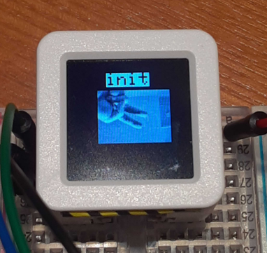 AtomS3からはカメラ画像確認できます。 ### アノテーション #### 画像の変換 まず、今回の方法で撮影した画像は特殊な形式になっているので、PNGに直す必要があります。 以下のPythonコードで簡単に実行できます。 ```Python:convert.py import argparse import os import cv2 import numpy as np def main(): parser = argparse.ArgumentParser( description="Convert raw 1200Byte(40x30) .simg files to PNG." ) parser.add_argument("input_dir", help="Input directory containing .simg files") parser.add_argument("output_dir", help="Output directory to store PNG images") args = parser.parse_args() input_dir = args.input_dir output_dir = args.output_dir WIDTH = 40 HEIGHT = 30 IMG_SIZE = WIDTH * HEIGHT if not os.path.exists(output_dir): os.makedirs(output_dir) for file_name in os.listdir(input_dir): if file_name.lower().endswith(".simg"): input_path = os.path.join(input_dir, file_name) with open(input_path, "rb") as f: raw_data = f.read() if len(raw_data) != IMG_SIZE: print(f"Skipping {file_name}: invalid data size ({len(raw_data)} bytes).") continue img_array = np.frombuffer(raw_data, dtype=np.uint8) img_array = img_array.reshape((HEIGHT, WIDTH)) base_name, _ = os.path.splitext(file_name) output_file_name = base_name + ".png" output_path = os.path.join(output_dir, output_file_name) cv2.imwrite(output_path, img_array) print(f"Saved {output_file_name}") print("Conversion finished.") if __name__ == "__main__": main() ``` 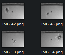 こんな感じの画像が撮影できてました! #### アノテーション作業 今回はドローンの姿勢(x,y,theta)を認識する特殊なタスクになるので、アノテーションツールも自作しました。 以下のPythonコードを起動したらマウスでポチポチすれば画面に赤い矢印が表示され、csvに姿勢データが保存されます。 ```Python:annotation.py import cv2 import os import sys import csv import math # Global variables for mouse click callback click_points = [] # Will store up to 2 points: [(x1, y1), (x2, y2)] # For visualization (absolute coordinates) annotation_points_abs = {} # { filename: (x1, y1, x2, y2) } # For normalized annotations (x, y, theta) annotations = {} # { filename: (norm_x, norm_y, norm_theta) } def mouse_callback(event, x, y, flags, param): global click_points if event == cv2.EVENT_LBUTTONDOWN: click_points.append((x, y)) def main(): # Get directory path from command line argument if len(sys.argv) < 2: print("Usage: python annotation.py [IMAGE_DIR]") sys.exit(1) image_dir = sys.argv[1] if not os.path.isdir(image_dir): print(f"Directory does not exist: {image_dir}") sys.exit(1) # Collect valid image files valid_extensions = [".jpg", ".jpeg", ".png", ".bmp", ".gif", ".tiff"] image_files = [ f for f in os.listdir(image_dir) if os.path.splitext(f.lower())[1] in valid_extensions ] image_files.sort() if not image_files: print("No image files found in the specified directory.") sys.exit(1) # Create an OpenCV window cv2.namedWindow("Annotation Tool", cv2.WINDOW_NORMAL) cv2.setMouseCallback("Annotation Tool", mouse_callback) # Current image index idx = 0 num_images = len(image_files) while True: filename = image_files[idx] filepath = os.path.join(image_dir, filename) img = cv2.imread(filepath) if img is None: print(f"Failed to load image: {filepath}") idx = (idx + 1) % num_images continue height, width = img.shape[:2] # Make a copy for drawing img_display = img.copy() # If there's already an annotation (arrow) for this image, draw it if filename in annotation_points_abs: x1_abs, y1_abs, x2_abs, y2_abs = annotation_points_abs[filename] cv2.arrowedLine( img_display, (int(x1_abs), int(y1_abs)), (int(x2_abs), int(y2_abs)), (0, 0, 255), # red color 1, # thickness tipLength=0.05 ) cv2.imshow("Annotation Tool", img_display) key = cv2.waitKey(10) & 0xFF # If two clicks have been made, calculate and store annotation if len(click_points) == 2: (x1, y1), (x2, y2) = click_points # Calculate normalized coordinates (for the first clicked point) norm_x1 = x1 / width norm_y1 = y1 / height # Calculate angle dx = x2 - x1 dy = y2 - y1 angle_rad = math.atan2(dy, dx) # range: -pi to pi if angle_rad < 0: angle_rad += 2 * math.pi # convert to 0 ~ 2*pi angle_rad -= math.pi if angle_rad < 0: print("RAD ERROR") return norm_theta = angle_rad / math.pi # normalize to 0 ~ 1 # Store the annotation in memory annotations[filename] = (norm_x1, norm_y1, norm_theta) annotation_points_abs[filename] = (x1, y1, x2, y2) print(f"[{filename}] x={norm_x1:.3f}, y={norm_y1:.3f}, theta={norm_theta:.3f}") # ====== Immediate visualization of the arrow ====== # Draw the arrow on the display copy cv2.arrowedLine( img_display, (int(x1), int(y1)), (int(x2), int(y2)), (0, 0, 255), 2, tipLength=0.05 ) # Show it again right away cv2.imshow("Annotation Tool", img_display) cv2.waitKey(10) # Clear the click points for the next annotation click_points.clear() # Key event handling if key == ord('q'): # Quit break elif key == ord('a'): # Left arrow key # Move to the previous image idx = (idx - 1) % num_images click_points.clear() elif key == ord('d'): # Right arrow key # Move to the next image idx = (idx + 1) % num_images click_points.clear() # Close the OpenCV window cv2.destroyAllWindows() # Write results to CSV csv_path = os.path.join(image_dir, "annotation.csv") with open(csv_path, mode='w', newline='', encoding='utf-8') as f: writer = csv.writer(f) # Header row writer.writerow(["x:image", "y1:result_x", "y2:result_y", "y3:result_theta"]) for fname in image_files: if fname in annotations: x_val, y_val, theta_val = annotations[fname] x_str = f"{x_val:.3f}" y_str = f"{y_val:.3f}" theta_str = f"{theta_val:.3f}" writer.writerow(["data/"+fname, x_str, y_str, theta_str]) else: # If no annotation was made for this file, leave blank writer.writerow(["data/"+fname, "", "", ""]) print(f"Annotation results saved to: {csv_path}") if __name__ == "__main__": main() ``` 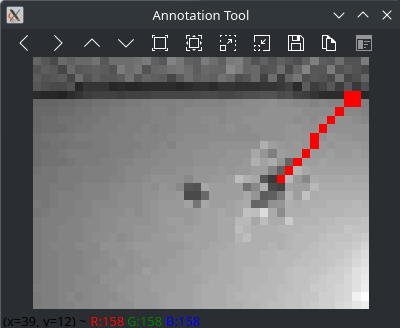 こんな感じでアノテーションしていきます。 保存されたcsvにはNeuralNetworkConsolで読み込める形式になっています。 ## NNCを用いた画像認識AIの作成
### 学習 いよいよ学習していきます!
いよいよ画像認識AIを作っていきます!
NeuralNetworkConsolで空のプロジェクトを作り、先に作成したデータセットを登録します。 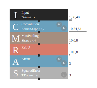 ネットワークはこんな感じになりました。 (チュートリアルで作ったものをほぼそのまま使いました) **学習実行!** NeuralNetworkConsolではボタンを押すだけで簡単に学習できます。 CPUだけでもこの程度の規模だとすぐに終わりますね。 **評価** 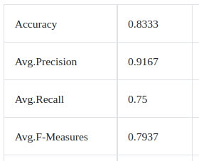 素人がとりあえず作ったネットワークなので精度は良くないですね。 **モデルの保存** モデルをnnb形式で保存してSDカードに入れておきましょう。 ## SPRESENSEによる推論 カメラで画像を撮影してドローン姿勢を推論、I2CでAtomS3に送信するスクリプトを作ります。 ```arduino:drone_autolanding.ino #include <Arduino.h> #include <Wire.h> #include <Camera.h> #include <SDHCI.h> #include <DNNRT.h> #define RAW_IMG_W CAM_IMGSIZE_QQVGA_H #define RAW_IMG_H CAM_IMGSIZE_QQVGA_V #define RESIZE_IMG_W RAW_IMG_W / 4 #define RESIZE_IMG_H RAW_IMG_H / 4 #define SLAVE_ADDRESS 0x08 SDClass sd; DNNRT dnnrt; DNNVariable input(RESIZE_IMG_W * RESIZE_IMG_H); void send_data(char* data, uint16_t length) { Wire.beginTransmission(SLAVE_ADDRESS); Wire.write(data, length); Wire.endTransmission(); // Serial.println("Data sent: " + data); } float mapf(float x, float in_min, float in_max, float out_min, float out_max) { return (x - in_min) * (out_max - out_min) / (in_max - in_min) + out_min; } void setup() { Serial.begin(115200); while (!sd.begin()){;} Serial.println("Insert SDCard"); Serial.println("Loading model ..."); Wire.begin(); File nnbfile = sd.open("drone.nnb"); int ret = dnnrt.begin(nnbfile); if (ret < 0) { Serial.println("dnnrt.begin failed"); return; } nnbfile.close(); theCamera.begin(); theCamera.setStillPictureImageFormat(CAM_IMGSIZE_QQVGA_H, CAM_IMGSIZE_QQVGA_V, CAM_IMAGE_PIX_FMT_YUV422); while (true) { CamImage img = theCamera.takePicture(); if(img.isAvailable()) { CamImage small; CamErr err = img.resizeImageByHW(small, RESIZE_IMG_W, RESIZE_IMG_H); if(!small.isAvailable()) { Serial.print("Clip and Reize Error:"); Serial.println(err); return; } small.convertPixFormat(CAM_IMAGE_PIX_FMT_RGB565); uint16_t* small_img_buff = (uint16_t*)small.getImgBuff(); float *calc_array = input.data(); float f_max = 0.0; for(int i = 0; i < RESIZE_IMG_W * RESIZE_IMG_H; i++) { calc_array[i] = (float)((small_img_buff[i] & 0x07E0) >> 5); if(calc_array[i] > f_max) f_max = calc_array[i]; } for(int i = 0; i < RESIZE_IMG_W * RESIZE_IMG_H; i++) { calc_array[i] /= f_max; } dnnrt.inputVariable(input, 0); dnnrt.forward(); DNNVariable output = dnnrt.outputVariable(0); int index = output.maxIndex(); Serial.println( String("X:") + String(output[0]) + String(", ") + String("y:") + String(output[1]) + String(", ") + String("θ:") + String(output[2])); // send data char data[3]; for (int i=0; i<3; i++) { data[i] = (char)mapf(output[i], 0.0, 1.0, 0.0, 255.0); } send_data(data, 3); } } } void loop() { } ``` **コードの要点** - データセットの作成時と同じように画像を縮小・正規化 - SDカードのモデルを読み込み、推論実行 - 推論結果をI2CでAtomS3に送信 **Spresense単体での試験** 推論自体がうまく行っているのかテストしてみました。 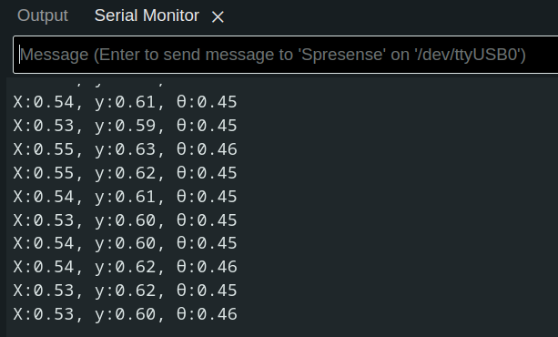 カメラにドローンを移すとシリアルモニタにそれっぽい値が! ## ドローンへのデータ送信 Spresenseから受け取ったデータをディスプレイに表示し、ドローンへ送信するプログラムを作ります。 今回使ったドローン(M5Stamp Fly)はesp_nowというwi-fiを使った通信方法を取っているので、同じ規格でブロードキャストします。 ```cpp:main.cpp #include <Arduino.h> #include <M5AtomS3.h> #include <esp_now.h> #include <esp_wifi.h> #include <WiFi.h> #include <Wire.h> #define SLAVE_ADDRESS 0x08 uint8_t data[3]; uint8_t broadcast_address[] = {0xFF, 0xFF, 0xFF, 0xFF, 0xFF, 0xFF}; esp_now_peer_info_t peer_info; bool recv_flag = false; void data_sent_cb(const uint8_t *macAddr, esp_now_send_status_t status) { USBSerial.print("ESP-NOW Send Status: "); USBSerial.println(status == ESP_NOW_SEND_SUCCESS ? "Success" : "Fail"); } float mapf(float x, float in_min, float in_max, float out_min, float out_max) { return (x - in_min) * (out_max - out_min) / (in_max - in_min) + out_min; } void wire_cb(int num_bytes) { recv_flag = true; int count = 0; while(Wire.available()) { data[count] = (uint8_t)Wire.read(); count++; } } void setup() { USBSerial.begin(9600); AtomS3.begin(); // AtomS3.Display.setRotation(); AtomS3.Display.setTextColor(AtomS3.Display.color565(0,0,0), AtomS3.Display.color565(255, 255, 255)); AtomS3.Display.setTextSize(2); // wire Wire.onReceive(wire_cb); Wire.setPins(38, 39); Wire.begin(SLAVE_ADDRESS); // esp now WiFi.mode(WIFI_STA); if (esp_now_init() != ESP_OK) { USBSerial.println("ESP-NOW init failed"); return; } esp_wifi_set_channel(3, WIFI_SECOND_CHAN_NONE); memset(&peer_info, 0, sizeof(peer_info)); memcpy(peer_info.peer_addr, broadcast_address, 6); peer_info.channel = 3; peer_info.encrypt = false; if (esp_now_add_peer(&peer_info) != ESP_OK) { USBSerial.println("Failed to add peer"); return; } WiFi.mode(WIFI_STA); WiFi.disconnect(); if (esp_now_init() == ESP_OK) { USBSerial.println("ESPNow Init Success"); } else { USBSerial.println("ESPNow Init Failed"); ESP.restart(); } esp_now_register_send_cb(data_sent_cb); AtomS3.Display.drawCentreString("init", 64, 10); AtomS3.update(); delay(1000); AtomS3.Display.clear(); } void loop() { if (!recv_flag) return; float x = mapf((float)data[0], 0.0, 255.0, -1.0, 1.0); float y = mapf((float)data[1], 0.0, 255.0, -1.0, 1.0); float theta = mapf((float)data[2], 0.0, 255.0, -1.0, 1.0); char str[32]; sprintf(str, "X :%5.2f", x); AtomS3.Display.drawCentreString(str, 64, 20); sprintf(str, "Y :%5.2f", y); AtomS3.Display.drawCentreString(str, 64, 50); sprintf(str, "TH:%5.2f", theta); AtomS3.Display.drawCentreString(str, 64, 80); AtomS3.update(); // send to fly esp_err_t result = esp_now_send(broadcast_address, data, sizeof(data)); if (result == ESP_OK) USBSerial.println("Message sent successfully"); else USBSerial.println("Error sending message"); } ``` 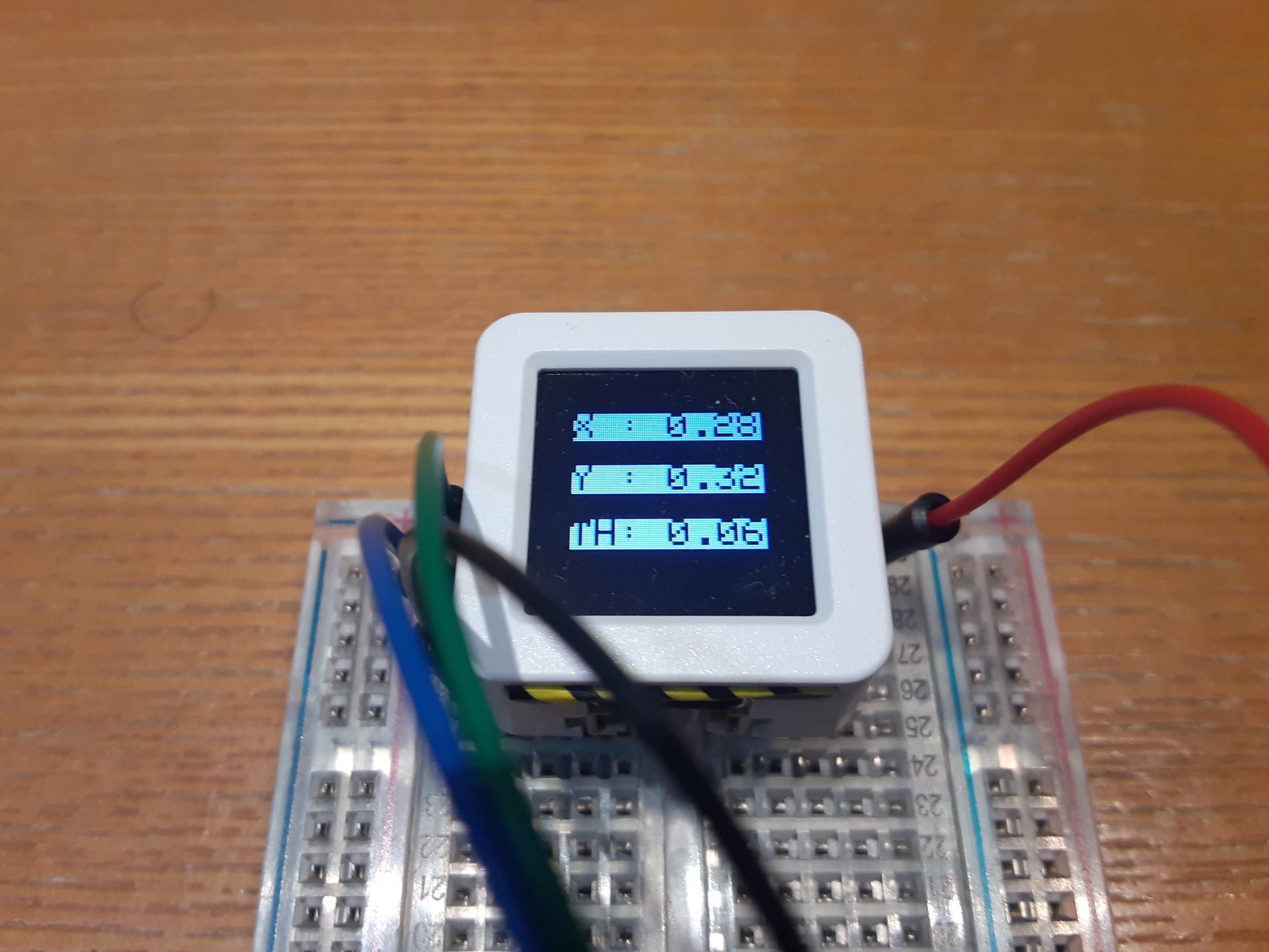 こんな感じで認識したドローンの姿勢が表示されています! SPRESENSEのシリアルモニタと見比べてもしっかり値が送信されていることがわかります。 ## 動作試験 実際にドローンパッドを設置して動かします! 数回実験してみてそれっぽく動いてくれたときの動画です。 @[youtube](https://www.youtube.com/watch?v=4ZoZ2dxLHi4) ドローンが緑に光ってから着陸態勢に入っています。 着陸台の上には乗れませんでしたが中心に行くようにがんばっているのが見て取れます。 ## 考察 ドローンが認識されたとおりに制御されていることは確認できましたが、着陸台の上に乗ることはできませんでした。 原因として、認識に時間がかかり制御周期が遅くなってしまっていること、カメラの視野角が狭くドローンがすぐにフェードアウトしてしまうなどが考えられます。 Spresenseのマルチコアをうまく活用すればもう少しうまく制御できたのかな... ## おわりに 今回は、Spresenseを使ってドローンの着陸の自動化にチャレンジしてみました。 Spresenseを使った画像認識は初めてでしたが、NeuralNetworkConsolのおかげで専門知識がなくても簡単に実現することができました。 開発環境としてArduino-IDEが提供されているので、すぐに開発に取り掛かることができたのも非常に楽しかったです。 GNSSなども使えるということでまだまだいろんなことに応用できそうです! (噂のIMUボードとGNSS機能を組み合わせてなにかできないか企んでいます...) 最後に、今回の記事作成にあたりSpresenseのモニタ提供をしていただきありがとうございました! また来年も挑戦しようと思います!