nichicon が 2021年10月10日12時32分50秒 に編集
ver 2.0の回路図等を追加
本文の変更
超小型のマイコンボードSeeeduino XIAOを使用したクレジットカードサイズのオシロスコープを作りました。 このマイコンボードに載っているマイコンのADコンバータは350kspsで動作します。 Arduino UNOや8bit PICマイコンと比べて3倍以上高速でサンプリングできます。 今回はこのサイズと高速ADCを活かしてオシロスコープを作りました。 グラフィックLCDの制御には、[しなぷすのハード製作記](https://synapse.kyoto/lib/MGLCD/page001.html)さんのMGLCDライブラリを使用しています。 # 部品
ver 1.0
・マイコンボード Seeeduino XIAO x1 ・グラフィックLCD AQM1248A x1 ・抵抗10kΩ x1 ・抵抗1MΩ x1 ・2ピンL型ピンヘッダ x1
ver 2.0 ・マイコンボード Seeeduino XIAO x1 ・グラフィックLCD AQM1248A x1 ・抵抗10kΩ x5 ・抵抗15kΩ x1 ・タクトスイッチ x3 ・3ピンL型ピンヘッダ x1
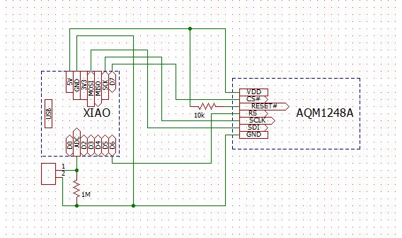
# 回路図
ver 1.0 注意:回路図ではLCDに5Vが供給されていますが正しくは3.3Vです。LCDは3V3のピンに繋いでください。
ver 2.0 サンプリングレートを変更するためにタクトスイッチを付けました。 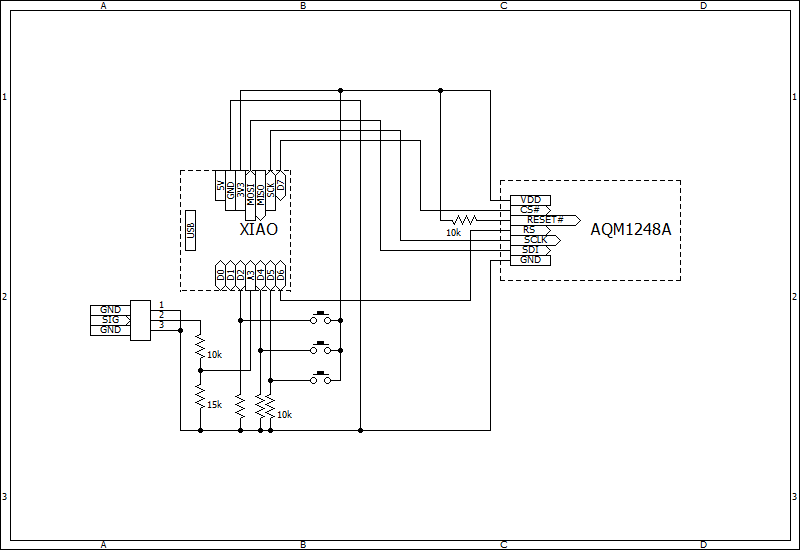
# プログラム ver 1.0 ``` #include <MGLCD.h> #include <MGLCD_SPI.h> #include <SPI.h> #define ADCpin A1 #define CS 7 #define DI 6 #define MAX_FREQ 8000000L MGLCD_AQM1248A_SPI MGLCD(MGLCD_SpiPin2(CS, DI), MAX_FREQ); #define time_width 50 //micro seconds | time_width > 3 uint16_t buf[100] ; uint32_t t0, dt ; uint8_t n, valY, lastY ; void set_screen(void){ MGLCD.Line(0,45, 0,47) ; MGLCD.Line(10,45, 10,47) ; MGLCD.Line(20,45, 20,47) ; MGLCD.Line(30,45, 30,47) ; MGLCD.Line(40,45, 40,47) ; MGLCD.Line(50,45, 50,47) ; MGLCD.Line(60,45, 60,47) ; MGLCD.Line(70,45, 70,47) ; MGLCD.Line(80,45, 80,47) ; MGLCD.Line(90,45, 90,47) ; MGLCD.Line(100,0, 100,47) ; MGLCD.Line(99,33, 101,33) ; MGLCD.Line(99,19, 101,19) ; MGLCD.Line(99,5, 101,5) ; MGLCD.Locate(17,0) ; MGLCD.print("3.3V") ; MGLCD.Locate(17,1) ; MGLCD.print("500u") ; } void setup() { // put your setup code here, to run once: pinMode(ADCpin, INPUT) ; MGLCD.Reset() ; } void loop() { // put your main code here, to run repeatedly: for(n=0; n<100; n++){ t0 = micros() ; dt = 0 ; buf[n] = analogRead(ADCpin) ; while(dt < time_width){ dt = micros() - t0 ; } } MGLCD.ClearScreen() ; set_screen() ; lastY = 47-(buf[0]/22) ; for(n=0; n<99; n++){ valY = 47-(buf[n+1]/22) ; MGLCD.Line(n,lastY, n+1,valY) ; lastY = valY ; } delay(1000) ; } ``` ver 2.0 タクトスイッチを追加してサンプリングレートを変更できるようにしました。
``` #include <MGLCD.h> #include <MGLCD_SPI.h> #include <SPI.h> #define ADCpin A3 #define CS 7 #define DI 6 #define MAX_FREQ 8000000L #define up_SW 4 #define down_SW 2 MGLCD_AQM1248A_SPI MGLCD(MGLCD_SpiPin2(CS, DI), MAX_FREQ) ; const uint16_t time_table[15] = {5, 10, 20, 30, 40, 50, 60, 80, 100, 200, 300, 500, 1000, 2000, 5000} ; static char table_index = 0 ; uint16_t buf[100] ; uint32_t t0, dt ; uint8_t n, valY, lastY ; uint8_t i ; void display_rate(void){ uint16_t time_width, dt_display ; MGLCD.Locate(17, 1) ; MGLCD.print(" ") ; MGLCD.Locate(17, 1) ; time_width = time_table[table_index] ; if(time_width > 99){ dt_display = time_width/100 ; MGLCD.printf("%dm", dt_display) ; }else{ dt_display = time_width*10 ; MGLCD.printf("%du", dt_display) ; } } void set_screen(void){ uint16_t dt_display ; MGLCD.Line(0,45, 0,47) ; MGLCD.Line(10,45, 10,47) ; MGLCD.Line(20,45, 20,47) ; MGLCD.Line(30,45, 30,47) ; MGLCD.Line(40,45, 40,47) ; MGLCD.Line(50,45, 50,47) ; MGLCD.Line(60,45, 60,47) ; MGLCD.Line(70,45, 70,47) ; MGLCD.Line(80,45, 80,47) ; MGLCD.Line(90,45, 90,47) ; MGLCD.Line(100,0, 100,47) ; MGLCD.Line(99,33, 101,33) ; MGLCD.Line(99,19, 101,19) ; MGLCD.Line(99,5, 101,5) ; display_rate() ; } void setup() { // put your setup code here, to run once: pinMode(ADCpin, INPUT) ; pinMode(up_SW, INPUT) ; pinMode(down_SW, INPUT) ; MGLCD.Reset() ; } void loop() { // put your main code here, to run repeatedly:
max_sample = 0 ; min_sample = 1023 ;
for(n=0; n<100; n++){ t0 = micros() ; dt = 0 ; buf[n] = analogRead(ADCpin) ;
while(dt < time_table[table_index]){
while(dt < (uint32_t)time_table[table_index]){
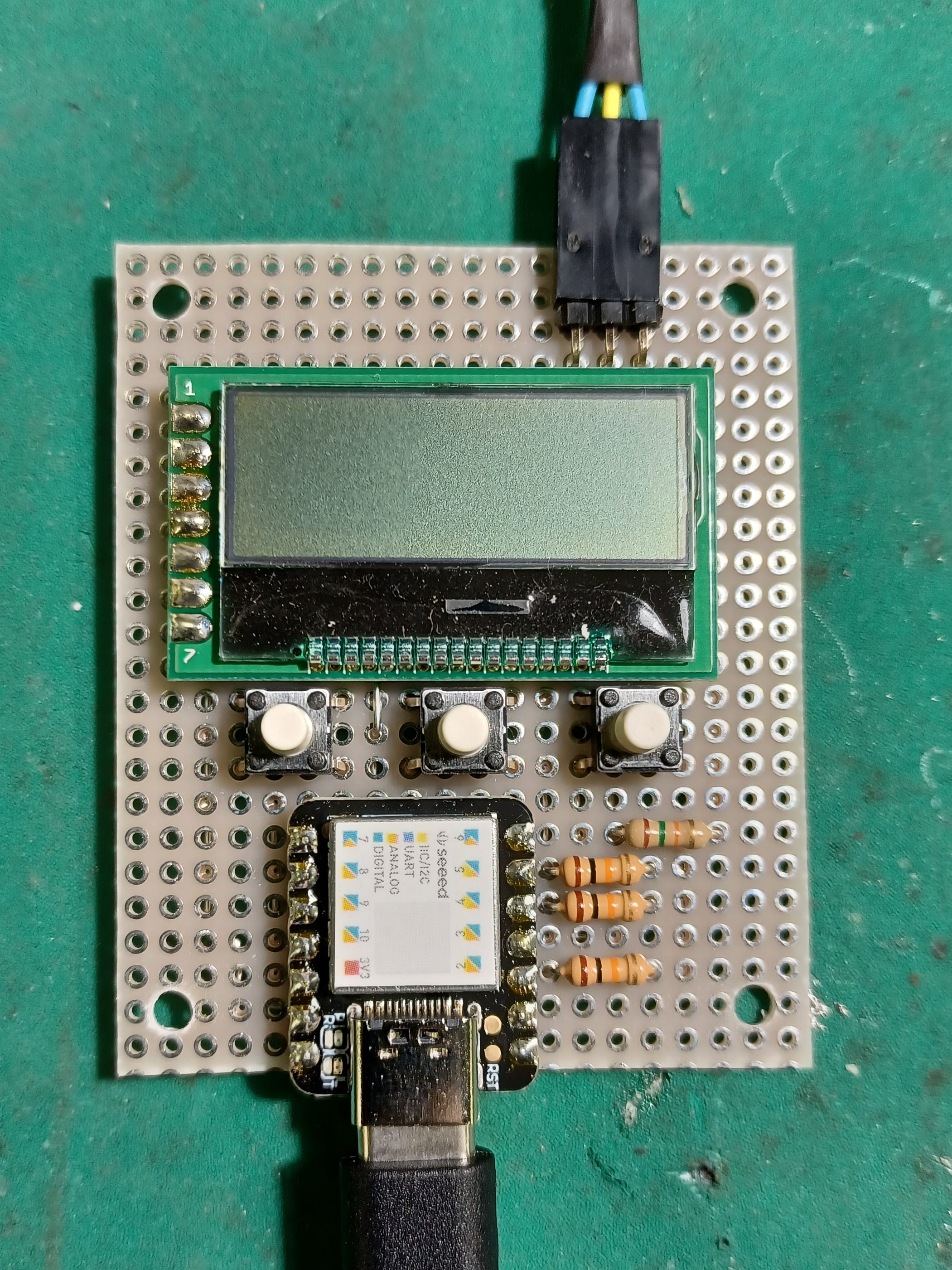
dt = micros() - t0 ; } } MGLCD.ClearScreen() ; set_screen() ; MGLCD.Locate(17,0) ; MGLCD.print("5.0V") ; MGLCD.Locate(17,5) ; MGLCD.print("0.0V") ; lastY = 47-(buf[0]/22) ; for(n=0; n<99; n++){ valY = 47-(buf[n+1]/22) ; MGLCD.Line(n,lastY, n+1, valY) ; lastY = valY ; } t0 = millis() ; dt = 0 ; while(dt < 1000){ if(digitalRead(up_SW) == 1){ table_index++ ; if(table_index > 14){ table_index = 14 ; } while(digitalRead(up_SW) == 1) ; delay(20) ; }else if(digitalRead(down_SW) == 1){ table_index-- ; if(table_index < 0){ table_index = 0 ; } while(digitalRead(down_SW) == 1) ; delay(20) ; } dt = millis() - t0 ; } } ``` # 作り方 ユニバーサル基板に回路図通りに配線して作ってください。 現状、サンプリングの間隔は50μsに固定されています。 プログラムを改造してサンプリングレートを変更できるようにすると使いやすくなります。
(10月10日追記) ver 2.0でサンプリングレートを変更できるようになりました。 また、入力に分圧回路を付けて5V入力に対応しました。
# 使い方 Seeeduino XIAOのType-Cコネクタにモバイルバッテリーなどで給電して、A1ピンに繋がっているL型ピンヘッダに信号を与えるとLCDに波形が表示されます。
(10月10日追記) ver 2.0はA3ピンが信号の入力です。
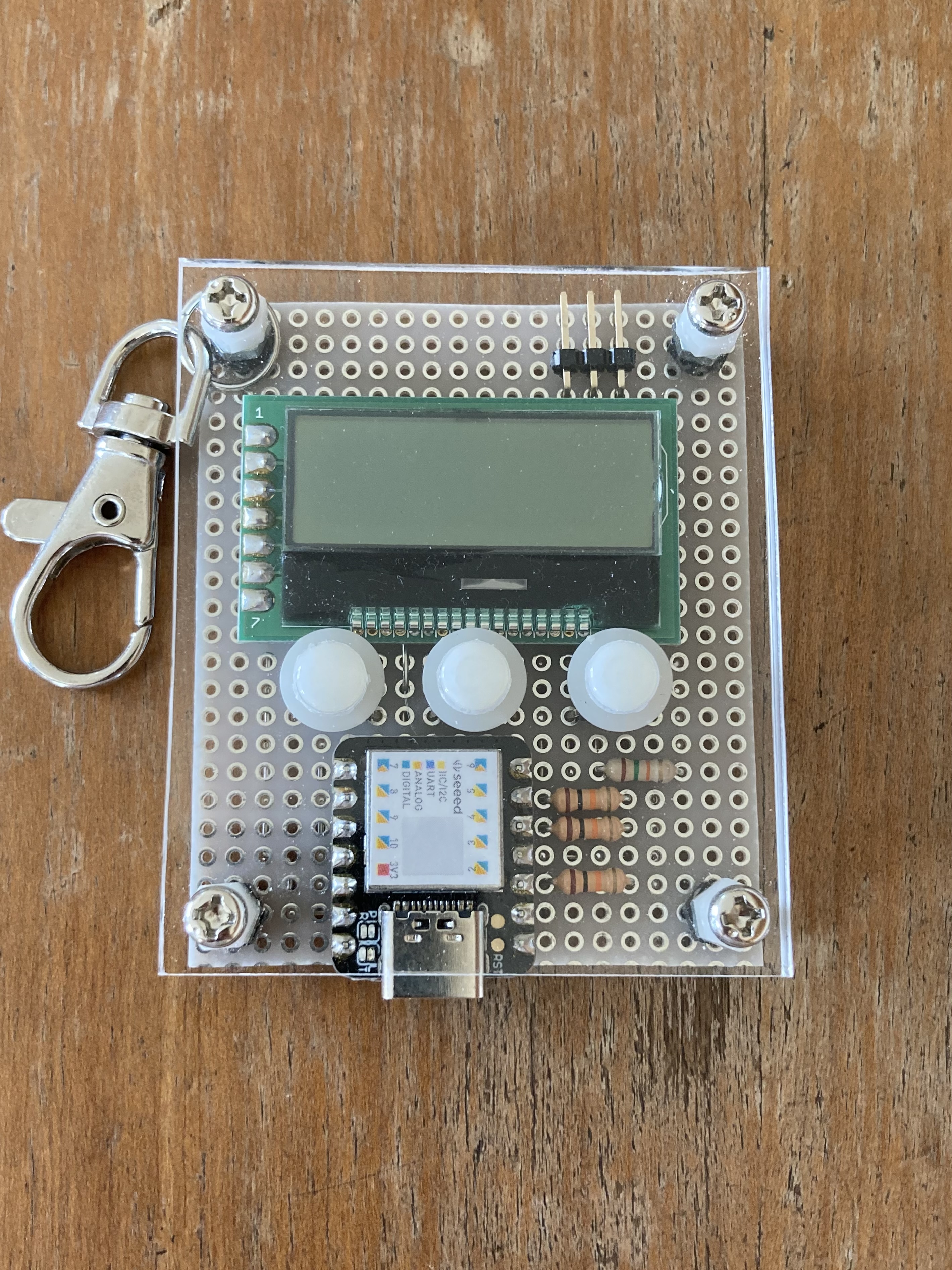
# 今後の改良予定 LCDの下のスペースが空いているので、そこにSeeeduino XIAOを入れることでさらに小型化できると考えています。 また、SeeeduinoとLCDをプリント基板に直接つければ薄型にできるので、機会があったら基板を発注しようと思います。 現在、電圧レンジの自動調整機能を作っているので完成したら更新します。
サンプリングレートの自動調整も試してみましたが、難しいので手動で変更できる仕様にする予定です。
サンプリングレートの自動調整も試してみましたが、難しいので手動で変更できる仕様にする予定です。→ver 2.0で機能を実装しました。 現在はUSB給電式ですが、ver3.0でリポバッテリーを搭載したいと考えています。