nichicon が 2021年02月28日18時59分51秒 に編集
コメント無し
本文の変更
Arduinoの自動書き込みにも使えるUSBシリアル変換器をPICで作りました。 これがあれば高いUSBシリアル変換モジュールを買う必要はありません。 Arduinoへの自動書き込みに対応するため、DTRピンを使えるようにしてあります。 ボーレートは115.2kbpsです。 # 材料 ・USBコネクター x1 ・PIC16F1455-I/P x1 ・積層セラミックコンデンサー0.1uF x1 ・1x5のピンヘッダ x1 # プログラム MPLAB X IDEのMPLAB Code Configurator(MCC)を使います。 以下の画像を参考にしてMCCで設定してください。設定が完了したらgenarateボタンでプログラムを生成します。 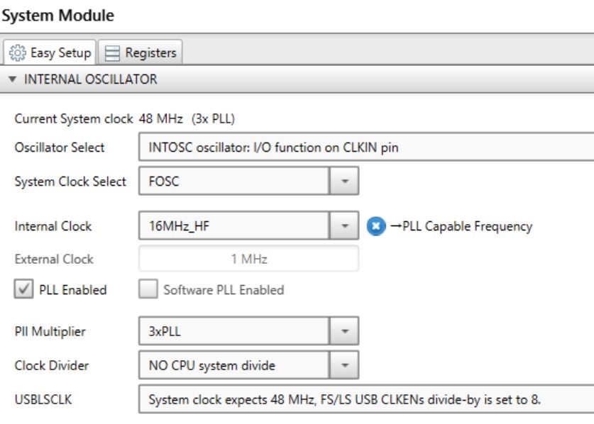 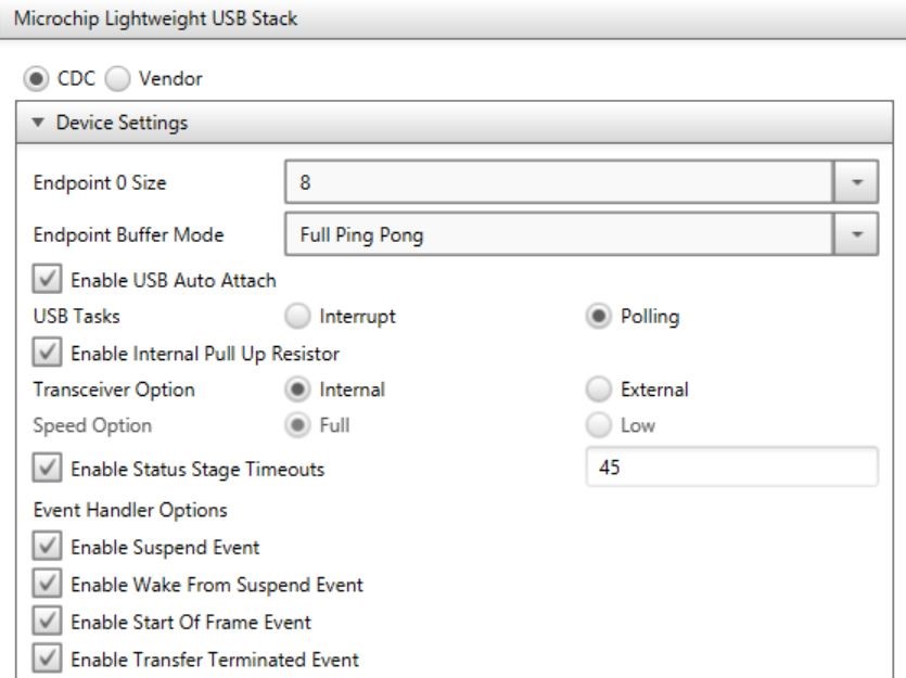 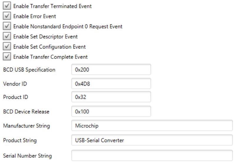 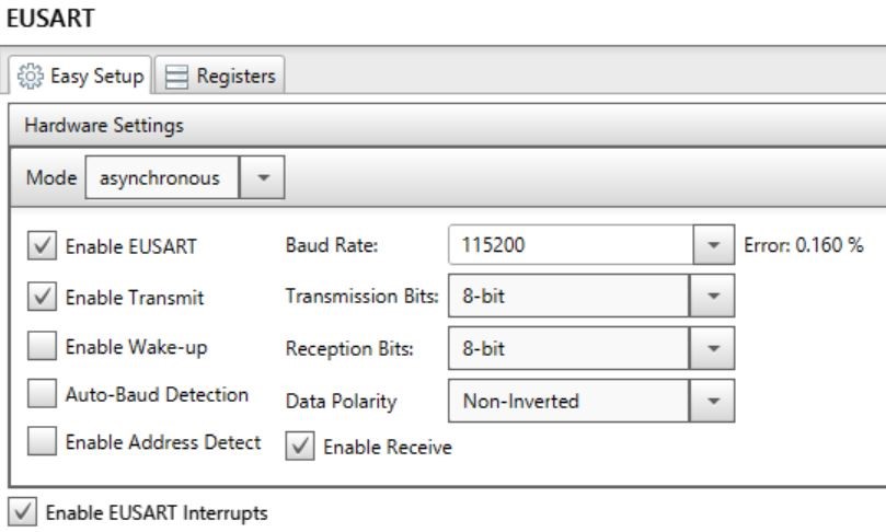 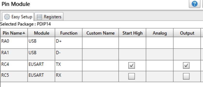 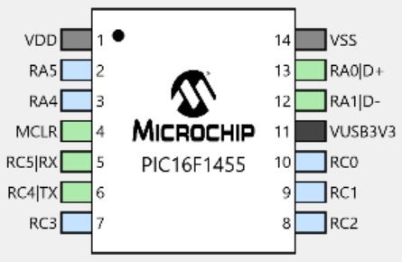 MCCの設定が完了したらプログラムを書いていきます。 まず、USB_device_CDC.cを書き換えます。 下の画像のように117行目のUART_DTRにPORTCbits.RC3を設定してください。書き換えるのはこの部分だけです。 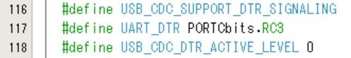 次にmain.cにプログラムを書きます。 以下にmain.cを載せておくのでコピペして使ってください。 #include "mcc_generated_files/mcc.h" #define No_Busy 0 #define Busy 1 #define data_buffer_size 64 static uint8_t USARTdata[data_buffer_size] ; uint8_t USART_ready = 0 ; uint8_t USARTdata_size = 0 ; uint8_t USART_index = 0 ; static uint8_t USBdata[data_buffer_size] ; uint8_t USB_index = 0 ; void main(void) { // initialize the device SYSTEM_Initialize(); // Enable the Global Interrupts INTERRUPT_GlobalInterruptEnable(); // Enable the Peripheral Interrupts INTERRUPT_PeripheralInterruptEnable(); TRISCbits.TRISC2 = 0 ; PORTCbits.RC2 = 1 ; TRISCbits.TRISC3 = 0 ; while (1) { USBDeviceTasks() ; if(USBGetDeviceState() < CONFIGURED_STATE || USBIsDeviceSuspended()== true){ continue ; } USBCheckCDCRequest() ; if(EUSART_is_rx_ready() == true){ USBdata[USB_index] = EUSART_Read() ; USB_index++ ; USBdata[USB_index] = 0 ; } if(USBUSARTIsTxTrfReady() == true && USB_index > 0){ putUSBUSART(USBdata, USB_index) ; USB_index = 0 ; } CDCTxService() ; if(USART_ready == No_Busy){ USARTdata_size = getsUSBUSART(USARTdata, sizeof(USARTdata)) ; if(USARTdata_size > 0){ USART_ready = Busy ; USART_index = 0 ; } } if(EUSART_is_tx_ready() == true && USART_ready == Busy){ EUSART_Write(USARTdata[USART_index]) ; USART_index++ ; if(USART_index == USARTdata_size){ USART_ready = No_Busy ; } } } } /** End of File */
USBCheckCDCRequest();を入れる事でDTRピンを使えるようになります。
# 回路図 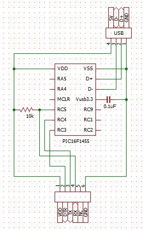
# 作り方 まずPICに上記のプログラムを書き込みます。 次にUSBコネクターのD+とD-をそれぞれPICのUSBピンと接続します。VUSB3V3とGNDの間に0.1uFのコンデンサーを入れます。 最後にTXピンとRXピン、そしてDTRピンを使いやすいように引きだしてピンヘッダに配線したら完成です。 # 使い方 USBシリアル変換器のTXピンとRXピンを通信する相手のRXピン、TXピンと接続します。 この状態でUSBシリアル変換器として使うことができます。 さらにArduinoへの書き込みに使う場合は、先程の接続に加えてDTRピンとATmega328PのRSTピンを0.1uFのコンデンサーで接続しRSTピンを10kΩでプルアップします。 書き込み時に自動でリセットするので自動でファームウェアを書き込む事ができます。