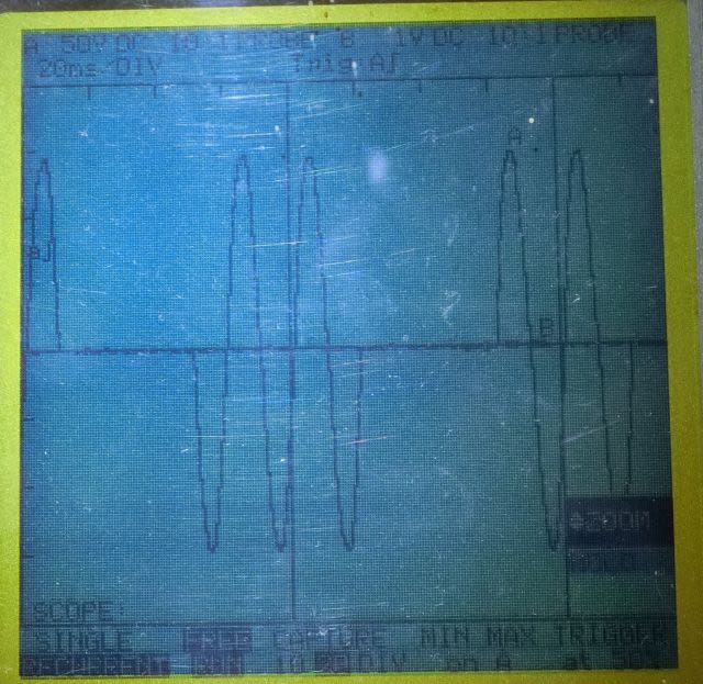
サイクル制御で SSRの出力を12.5%~100%の範囲で 8段階にコントロールするボードです。
最終的には ヒータによる温度制御ができるよう、熱電対も接続してあります。
主要部品:
| No. | 部品名 | 型番 他 |
|---|---|---|
| 1 | CPU | ATmega328P |
| 2 | ダイオード・ブリッジ | |
| 3 | 整流用ダイオード | |
| 4 | フォトカプラ | PC817 |
| 5 | 電解コンデンサ | |
| 6 | K型熱電対モジュール | 秋月電子 M-08218 |
| 7 | 16×2 LCDモジュール | 秋月電子 P-00040 |
| 8 | ロータリーエンコーダ | 秋月電子 P-05773 |
| 9 | SSRキット | 秋月電子 K-00210 |
| 10 | 端子台 | サトーパーツ ML-20-2P |
| 11 | 電源トランス | 豊澄 HT-605 |
| 12 | 電源スイッチ | ミヤマ DS-059K |
| 13 | 電源コード | |
| 14 | ケース | タカチ YM-200 |
SSR_ctrlのソース
// include the library code:
#include "Adafruit_SPIDevice.h"
#include "Adafruit_MAX31855.h"
#include <LiquidCrystal.h>
// Example creating a thermocouple instance with software SPI on any three
// digital IO pins.
#define MAXDO 12
#define MAXCS 10
#define MAXCLK 13
#define ZC 14
#define ZCMsk 0x01 // (0000 000x): PINC
#define ENC_SW 15
#define ENC_A 16
#define ENC_B 17
#define EncMsk 0x0c // (0000 xx00): PINC
#define EncMskA 0x04 // (0000 0x00): PINC
#define EncMskB 0x08 // (0000 x000)
#define ssr 21
#define dSSR 0x80 // (1xxx xxxx): PORTB
// (fSense)
#define bSens_En 1 // (xxxx xxx1)
#define bSens_Zc 2 // (xxxx xx1x)
// (enc_count)
#define enc_min 1
#define enc_max 8
// Initialize the Thermocouple
Adafruit_MAX31855 thermocouple(MAXCLK, MAXCS, MAXDO);
// initialize the library by associating any needed LCD interface pin
// with the arduino pin number it is connected to
const int rs = 8, rw = 7, en = 6, d4 = 2, d5 = 3, d6 = 4, d7 = 5;
LiquidCrystal lcd(rs, en, d4, d5, d6, d7);
byte enc_count=enc_min;
long lcd_tim0, sens_tim0;
byte fSens, sens_cnt, sensDat, sensBak, sensd[4];
byte fZC, zc_count;
//*****
void setup() {
pinMode(rw, OUTPUT);
digitalWrite(rw, LOW); // LCD R/W = "0" : write
DDRB |= 0x80; // (oxxx xxxx)
digitalWrite(ssr, LOW); // SSR off
pinMode(ZC, INPUT);
pinMode(ENC_A, INPUT);
pinMode(ENC_B, INPUT);
// set up the LCD's number of columns and rows:
lcd.begin(16, 2);
lcd.clear();
delay(3);
lcd.print("MAX31855 test");
// wait for MAX chip to stabilize
delay(500);
if (!thermocouple.begin()) {
lcd.print("ERROR.");
while (1) delay(10);
}
lcd.print("DONE.");
delay(300);
lcd.clear();
lcd.setCursor(0, 0);
lcd.print("Int.= ");
lcd_tim0 = 100; // ms
sens_tim0= 300; // us
fSens = 0;
sens_cnt = 0;
sensd[0] = PINC;
sensd[1] = PINC;
sensd[2] = PINC;
sensd[3] = PINC;
sensBak = PINC;
sensDat = PINC;
}
void loop() {
show_Temp();
chk_sensor();
chk_enc();
chk_zc();
ssr_ctrl();
}
void ssr_ctrl() {
if ( (fZC & 0x01) != 0) {
if ( (zc_count & 0x07) < enc_count) {
PORTB |= dSSR; // (1xxx xxxx) :SSR on
} else {
PORTB &= !dSSR; // (0xxx xxxx) :SSR off
}
fZC = fZC << 1;
}
}
void chk_zc() {
if ( (fSens & bSens_Zc) != 0) {
if ( (((sensBak ^ sensDat) & sensDat) & ZCMsk) != 0) {
zc_count++;
fZC = 0x01; // (0000 0001)
}
fSens = fSens << 1;
}
}
void chk_enc() {
byte dat;
if ( (fSens & bSens_En) != 0) {
if ( (((sensBak ^ sensDat) & sensDat) & EncMskA) != 0) { // change Phase A: "0" => "1"
if ( (sensDat & EncMskB) == 0) { if (enc_count < enc_max) { enc_count ++;} }
else {if (enc_count > enc_min) { enc_count --;} }
}
fSens = fSens << 1;
}
}
void chk_sensor() {
if ( (micros() - sens_tim0) > 100) { //0.1ms
sens_tim0 = micros();
sensBak = sensDat;
sensd[(sens_cnt & 3)] = PINC;
sens_cnt++;
sens_cnt &= 3; // (0000 00xx)
sensDat |= (sensd[0] & sensd[1] & sensd[2] & sensd[3]);
sensDat &= (sensd[0] | sensd[1] | sensd[2] | sensd[3]);
fSens =0x01; // (0000 0001)
}
}
void show_Temp() {
byte dat;
if ( (millis() - lcd_tim0) > 300) { // 0.3s
lcd_tim0 = millis();
// basic readout test, just print the current temp
lcd.setCursor(6, 0);
lcd.print(thermocouple.readInternal());
double c = thermocouple.readCelsius();
lcd.setCursor(0, 1);
if (isnan(c))
{
lcd.print("T/C Problem");
}
else
{
lcd.print("T/C = ");
lcd.print(c);
}
lcd.setCursor(12, 1);
dat = sensDat;
if (dat < 0x10) { lcd.print("0"); }
lcd.print(dat, HEX);
lcd.print(" ");
lcd.print(enc_count, HEX);
}
}投稿者の人気記事


-
marua
さんが
2021/02/27
に
編集
をしました。
(メッセージ: 初版)
-
marua
さんが
2021/02/27
に
編集
をしました。
(メッセージ: 出力波形&I/O一覧追加)
-
marua
さんが
2021/02/27
に
編集
をしました。
(メッセージ: 回路図 追加)
ログインしてコメントを投稿する