

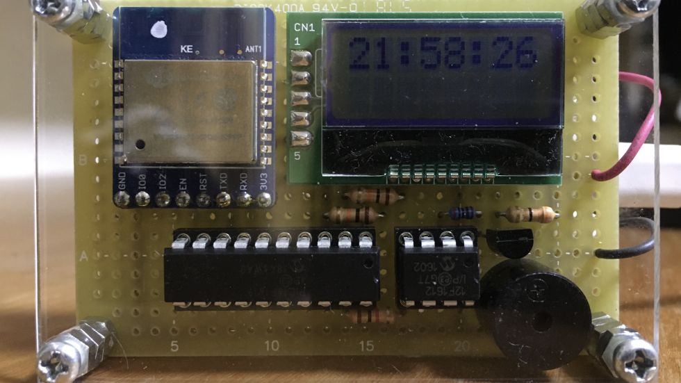
NTP(Network Time Protocol)サーバーから情報を取得して自動で時刻を合わせる目覚まし時計を作りました。消費電力を抑えるために、時刻調整する時以外はESPを無効にしています。
電源を接続した時と午前0:00に自動で時刻を合わせるので難しい操作はありません。
材料
①PIC16F1619 x1
②PIC12F1612 x1
③ESP-WROOM-02 x1
④AQM0802A x1
⑤抵抗10kΩ x3
⑥抵抗2kΩ x1
⑦抵抗1kΩ x1
⑧抵抗33Ω x1
⑨2SC1815Y x1
⑩圧電スピーカー x1
11.ユニバーサル基板 Cタイプ x1
回路図
プログラム
PIC16F1619用のファームウェア
#include "mcc_generated_files/mcc.h"
#include <stdio.h>
const uint8_t call_time[3] = {6, 0, 0} ;
union {
uint32_t ltime ;
uint8_t ctime[4] ;
}time;
uint8_t buffer[128] ;
uint32_t temp ;
uint8_t t1_cnt, t1_flag ;
uint16_t t3_cnt ;
uint8_t t3_flag ;
//AT commands
const uint8_t mode[] = "AT+CWMODE=1\r\n" ;
const uint8_t mult[] = "AT+CIPMUX=1\r\n" ;
const uint8_t join[] = "AT+CWJAP="WiFi_SSID","WiFi_PASS"\r\n" ;
const uint8_t open[] = "AT+CIPSTART=1,"UDP","ntp.nict.jp",123,,0\r\n" ;
const uint8_t send[] = "AT+CIPSEND=1,48\r\n" ;
const uint8_t close[] = "AT+CIPCLOSE=1\r\n" ;
const uint8_t shut[] = "AT+CWQAP\r\n" ;
const uint8_t data[] = {0x0B, 0x00, 0x00, 0x00, 0x00, 0x00, 0x00, 0x00,
0x00, 0x00, 0x00, 0x00, 0x00, 0x00, 0x00, 0x00,
0x00, 0x00, 0x00, 0x00, 0x00, 0x00, 0x00, 0x00,
0x00, 0x00, 0x00, 0x00, 0x00, 0x00, 0x00, 0x00,
0x00, 0x00, 0x00, 0x00, 0x00, 0x00, 0x00, 0x00,
0x00, 0x00, 0x00, 0x00, 0x00, 0x00, 0x00, 0x00} ;
void error_check(){
if(OERR || FERR){
RCSTA = 0 ;
RCSTA = 0x90 ;
}
}
void Send_cmd(const uint8_t *cmd){
while(*cmd != 0){
EUSART_Write(*cmd++) ;
}
__delay_ms(1000) ;
}
void send_str(const uint8_t *str, uint8_t cnt){
while(cnt != 0){
EUSART_Write(*str++) ;
cnt-- ;
}
}
void receive(uint8_t *buf){
uint8_t *ptr, rcv, cnt ;
cnt = 0 ;
ptr = buf ;
TMR3ON = 1 ;
do{
error_check() ;
if(EUSART_is_rx_ready()){
rcv = EUSART_Read() ;
if(rcv == '\n'){
ptr = buf ;
cnt = 0 ;
}else{
*ptr = rcv ;
ptr++ ;
cnt++ ;
}
}
if(t3_flag){
return ;
}
}while(cnt < 58) ;
TMR3ON = 0 ;
}
void get_time(uint32_t bin){
EN_PORT = 1 ;
__delay_ms(1000) ;
Send_cmd(shut) ;
Send_cmd(mode) ;
Send_cmd(mult) ;
Send_cmd(join) ;
__delay_ms(6000) ;
Send_cmd(close) ;
Send_cmd(open) ;
__delay_ms(2000) ;
Send_cmd(send) ;
send_str(data, 48) ;
receive(buffer) ;
Send_cmd(close) ;
EN_PORT = 0 ;
time.ctime[3] = buffer[50] ;
time.ctime[2] = buffer[51] ;
time.ctime[1] = buffer[52] ;
time.ctime[0] = buffer[53] ;
bin = time.ltime ;
}
void I2C_Master_Wait(){
while ((SSP1STAT & 0x04) || (SSP1CON2 & 0x1F)); //Transmit is in progress
}
void I2C_start(){
I2C_Master_Wait();
SSP1CON2bits.SEN = 1; //Initiate start condition
}
void I2C_RepeatedStart(){
I2C_Master_Wait();
SSP1CON2bits.RSEN = 1; //Initiate repeated start condition
}
void I2C_stop(){
I2C_Master_Wait();
SSP1CON2bits.PEN = 1; //Initiate stop condition
}
void I2C_write(unsigned char d){
I2C_Master_Wait();
SSP1BUF = d; //Write data to SSPBUF
}
unsigned char I2C_read(unsigned char a){
unsigned char temp;
I2C_Master_Wait();
SSP1CON2bits.RCEN = 1;
I2C_Master_Wait();
temp = SSP1BUF; //Read data from SSPBUF
I2C_Master_Wait();
SSP1CON2bits.ACKDT = a; //Acknowledge bit
SSP1CON2bits.ACKEN = 1; //Acknowledge sequence
return temp;
}
void send_cmd(uint8_t cmd){
I2C_start() ;
I2C_write(0x7C) ;
I2C_write(0x00) ;
I2C_write(cmd) ;
I2C_stop() ;
}
void LCD_init(){
__delay_ms(40) ;
send_cmd(0x38) ;
__delay_us(27) ;
send_cmd(0x39) ;
__delay_us(27) ;
send_cmd(0x14) ;
__delay_us(27) ;
send_cmd(0x70) ;
__delay_us(27) ;
send_cmd(0x56) ;
__delay_us(27) ;
send_cmd(0x6C) ;
__delay_ms(250) ;
send_cmd(0x38) ;
__delay_us(27) ;
send_cmd(0x0C) ;
__delay_us(27) ;
send_cmd(0x01) ;
__delay_ms(2) ;
}
void send_data(uint8_t data){
I2C_start() ;
I2C_write(0x7C) ;
I2C_write(0x40) ;
I2C_write(data) ;
I2C_stop() ;
}
void LCD_write(uint8_t ddram, uint8_t *text, uint8_t num){
uint8_t i ;
for(i=0; i<num; i++){
send_cmd(0x80 | ddram) ;
send_data(text[i]) ;
ddram++ ;
}
}
void tmr1_isr(void){
t1_cnt++ ;
if(t1_cnt >= 20){
t1_cnt = 0 ;
t1_flag = 1 ;
}
}
void tmr3_isr(void){
t3_cnt++ ;
if(t3_cnt >= 1000){
t3_cnt = 0 ;
t3_flag = 1 ;
}
}
void putch(char c){
send_data(c) ;
}
void main(void)
{
uint32_t bin_data ;
uint8_t h = 23 ;
uint8_t m = 59 ;
uint8_t s = 59 ;
uint8_t set_flag ;
// initialize the device
SYSTEM_Initialize();

TMR1_SetInterruptHandler(tmr1_isr) ;
TMR3_SetInterruptHandler(tmr3_isr) ;

// Enable the Global Interrupts
INTERRUPT_GlobalInterruptEnable();

// Enable the Peripheral Interrupts
INTERRUPT_PeripheralInterruptEnable();

TMR3ON = 0 ;
SSP1CON1bits.SSPEN = 1 ;
LCD_init() ;

while (1)
{
    if(t1_flag == 1){
        t1_flag = 0 ;
        s++ ;
        if(s >= 60){
            s = 0 ;
            m++ ;
            if(m >= 60){
                m = 0 ;
                h++ ;
                if(h >= 24){
                    h = 0 ;
                    set_flag = 1 ;
                }
            }
        }
    }
    send_cmd(0x80) ;
    printf("%2d:%2d:%2d", h, m, s) ;

    if(h == call_time[0]){
        if(m == call_time[1]){
            if(s == call_time[2]){
                alarm_PORT = 1 ;
            }else if(s == (call_time[2]+1)){
                alarm_PORT = 0 ;
            }
        }
    }

    if(set_flag == 1){
        set_flag = 0 ;
        get_time(bin_data) ;
        time.ctime[3] = buffer[50] ;
        time.ctime[2] = buffer[51] ;
        time.ctime[1] = buffer[52] ;
        time.ctime[0] = buffer[53] ;
        temp = time.ltime ;
        temp = temp + 9*3600 ;
        if(temp > 36524*86400ul){
            while(temp >= 86400){
                temp -= 86400 ;
            }
            s = temp%60 ;
            temp /= 60 ;
            m = temp%60 ;
            temp /= 60 ;
            h = temp%24 ;
        }
    }
}
}
PIC12F1612用のファームウェア
#include "mcc_generated_files/mcc.h"
void main(void)
{
uint8_t state, i ;
// initialize the device
SYSTEM_Initialize();
while (1)
{
    if(trig_PORT == 1){
        state = 1 ;
    }
    if(state == 1){
        for(i=0; i<20; i++){
            CCPR1L = 0xC7 ;
            __delay_ms(200) ;
            CCPR1L = 0 ;
            __delay_ms(500) ;
        }
        state = 0 ;
    }
}
}
作り方
①PIC16F1619とPIC12F1612にプログラムを書 き込む。
②基板に回路図通りに配線し回路を作る。
③アクリル板を基板と同じサイズに切り、四隅 にネジ穴をあける。
④アクリル板と基板をネジでとめて完成!
投稿者の人気記事


-
nichicon
さんが
2020/12/26
に
編集
をしました。
(メッセージ: 初版)
-
nichicon
さんが
2020/12/26
に
編集
をしました。
-
nichicon
さんが
2020/12/27
に
編集
をしました。
-
nichicon
さんが
2020/12/27
に
編集
をしました。
-
nichicon
さんが
2021/02/20
に
編集
をしました。
-
nichicon
さんが
2021/02/22
に
編集
をしました。
-
nichicon
さんが
2021/02/22
に
編集
をしました。
-
nichicon
さんが
2021/02/22
に
編集
をしました。
-
nichicon
さんが
2021/02/27
に
編集
をしました。
-
nichicon
さんが
2021/12/09
に
編集
をしました。
ログインしてコメントを投稿する